| C H A P T E R 4 |
|
Connecting Your SCSI Array |
This chapter provides procedures for cabling the Sun StorEdge 3120 SCSI array for single-bus or split-bus configurations and for connecting the array to power and to network devices.
The topics covered in this chapter are as follows:
Before you connect the Sun StorEdge 3120 SCSI array to the network, position the Sun StorEdge 3120 SCSI array in the rack or in the location where it will remain.

|
Caution - When you power off the array, wait five seconds before you power it back on. If you power the array off and on too quickly, a race condition might occur. |
The bezel on your array has two locks whose keys can be removed when the locks are in either the locked or open position. It is possible to reconfigure the locks so that the keys cannot be removed.

To change the locks so the keys cannot be removed, follow these steps:
1. Remove the bezel by gently pivoting the swing arms out of their ear sockets, and make sure the key is in the locked position, with the pawl extending horizontally past the edge of the bezel (see the first panel of FIGURE 4-2).
2. Hold the key in place and use a 12 mm or 3/8-inch nut driver to remove the locking nut that holds the pawl in place as shown in the first panel of FIGURE 4-2.

|
Caution - Be sure to hold the key in place. Otherwise there is a risk of breaking the small tab on the lock that serves as a stop. |
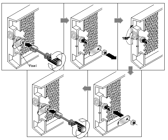
3. Lift the pawl off the threaded part of the lock body, as shown in the second panel of FIGURE 4-2.
4. Set the pawl aside, face up, so that you can remember its orientation when you replace it.
5. Use the key to turn the lock 180 degrees, as shown in the third panel of FIGURE 4-2.
6. Replace the pawl in the same orientation as before, as shown in the fourth panel of FIGURE 4-2.
7. Hold the key in place and use the nut driver to refasten the locking nut that holds the pawl in place, as shown in the fifth panel of FIGURE 4-2. Be careful not to cross-thread the nut.

|
Caution - Be sure to hold the key in place. Otherwise there is a risk of breaking the small tab on the lock that serves as a stop. |
|
Note - To convert your bezel locks back so that the keys can be removed, repeat the preceding steps. |
To rackmount the array in a rack or a cabinet, refer to the installation manual which is provided with the rack or refer to the Sun StorEdge 3000 Family Rack Installation Guide for 1U Arrays on the product website.
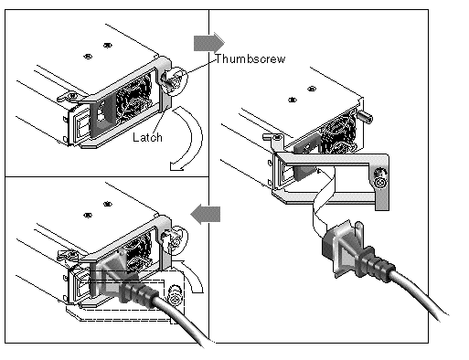
When you connect the AC power cords, you should install the provided two cord locks at the same time. To connect the AC power cords, perform the following procedure.
1. Connect an appropriate AC power cable to the first power supply and to a power outlet.
The provided AC cord locks are used to securely fasten the AC cable connectors.

|
Caution - For AC power: If the array is connected to AC power sources not within the designated 90-264 VAC range, damage might occur to the unit. |
|
Note - To ensure power redundancy, be sure to connect the two power supply modules to two separate circuits (for example, one commercial circuit and one UPS). |
2. Use a screwdriver to remove the screw from one of the two cord locks provided.
3. Turn the thumbscrew of the green ejector handle counterclockwise to release the handle.
4. Pull the green ejector handle of the first power supply forward, and slide the cord lock around the handle and around the AC power connector on the power supply.
The cord lock fits very snugly around the power cable connector.
5. Slide the cord lock screw through the cord lock holes, and tighten the screw with a screwdriver.
Close the green ejector handle, and turn the thumbscrew clockwise to close the handle.
6. Repeat steps 2 through 5 for the second cord lock and second power cable.
Two DC power cords are packaged with each DC array. To connect the DC power cords, perform the following procedure.
1. Connect a DC power cable to the first power supply and to a power outlet.
|
Note - Use only the DC power cables provided with the array. |
2. Check the DC cable part number and wire labels carefully before connecting the cable to the source.

|
Caution - If the Sun StorEdge 3120 SCSI array is connected to DC power sources not within the designated -48V DC (-36 VDC to -72 VDC) range, damage might occur to the unit. |
|
Note - To ensure power redundancy, be sure to connect the two power supply modules to two separate circuits (for example, one commercial circuit and one UPS). |
|
Note - To extend the length of the DC power cable as needed, strip the last 1/4 inch of the cable, insert the stripped end into a provided Panduit tube, and crimp the tube. |
3. Tighten the cable locking screws to attach the cable securely to the power supply power outlet.
4. Connect the second power cable to the second power supply and to a second power outlet. Tighten the cable locking screws.
If one power supply fails, the second power supply automatically takes the full load.
The SCSI specification states that the maximum bus length for Ultra320 SCSI is 12 meters (39.37 feet) for multidrop connections. The Sun StorEdge 3120 SCSI array uses a multidrop implementation. The ports on each channel are connected to the same physical SCSI bus.
Taking into account the internal bus length of .7 meters (2.3 feet), and the internal SCSI bus length of the host, the maximum SCSI bus length for each channel is 12 meters (39.37 feet) when connected to an LVD host adapter.
You must ensure that the length of all cables to any connected nodes, as well as the internal bus length of .7 meters (2.3 feet) internal to the Sun StorEdge 3120 SCSI array and the internal bus length of the host, is less than 12 meters (39.37 feet) in total. Also include the jumper cable length of .3 meters (.98 feet) if the JBOD is being used in a single-bus or multi-initiator configuration. In a dual-host, multi-initiator configuration, each host cable should be 5 meters (16.4 feet) or less.
The longest Ultra320 cable qualified by Sun is 10 meters (32.81 feet) in length.
When connected to single-ended host adapters, the longest supported bus length per channel is 2 meters (6.56 feet).
The following table summarizes the cable length requirements.
For a list of the SCSI cables available for the Sun StorEdge 3120, refer to the Sun StorEdge 3120 SCSI Array Release Notes.
You can connect a JBOD (Just a Bunch of Disks, no controller) array directly to a Sun host server using either single-bus or split-bus configurations. With the Sun StorEdge 3120 SCSI array, you can configure the following:
The array can be connected to a host by means of a 320 MB/second PCI Dual Ultra320 SCSI host adapter installed in a host.
Connect the array to one or two hosts with SCSI cables. The TERM LED is a solid green color when a drive is available for configuration. For details on the TERM LED, see Section 6.3, Back-Panel LEDs.

|
Caution - SCSI IDs are set based on the switch setting on the array when it is powered on. If you change the switch setting, the SCSI IDs will change after you power off, and then power on. For more details on switch settings, see Section 4.6.2, Fixed Drive IDs. |

|
Caution - You can connect or disconnect the I/O module's cables while the array is powered on but the SCSI host buses connected to the array must be inactive. |
The drive-bus configuration determines how drives and drive IDs are assigned to drive channels.
On the back panel of each unit, the SB icon indicates where to connect the SCSI jumper cable for a single-bus configuration. The SB icons are located next to the SCSI ports on the far right and on the far left.


Since no SCSI jumper cable is required for a split-bus configuration, there is no indicator icon.
|
Note - If a jumper cable is not attached to the JBOD, it is automatically a split-bus configuration. |
The SCSI IDs are also displayed on the lower inside-front edge of the chassis in front of each drive. These IDs are automatically assigned based on the switch setting. For more information on switch settings and drive IDs, see the following section, Section 4.6.2, Fixed Drive IDs.
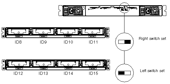
Drive IDs are not dependent on the configuration type. Single-bus and split-bus configurations use the same drive IDs. The IDs assigned for disks 0 through 3 depend on the switch settings on the JBOD array. IDs 5 and 6 are reserved for SCSI Accessed Fault-Tolerant Enclosure (SAF-TE) IDs. The fixed drive IDs for a 4-drive configuration are shown in FIGURE 4-6.

|
Caution - SCSI IDs are set based on the switch setting on the array when it is powered on. If you change the switch setting, the SCSI IDs will change after you power off, and then power on. |
The following table shows the drive IDs that correspond with the switches in FIGURE 4-6.
The IDs are also displayed on the lower inside-front edge of the chassis in front of each drive. These IDs are automatically assigned based on the switch setting as shown in FIGURE 4-6.
The following illustration shows the port names. The port names, A and B, are used for easy reference in the cabling procedures. In a single-bus configuration, the B Out and the A In ports are available for host connections. For more information, see Section 4.6.4, A Single-Bus JBOD with One Host Connection or Section 4.6.5, A Single-Bus, Multi-Initiator JBOD Configuration. In a split-bus configuration, several host connection configurations exist. For details, see Section 4.6.6, A Split-Bus, Single-Initiator JBOD Configuration or Section 4.6.7, A Split-Bus, Multi-Initiator JBOD Configuration Connected to One JBOD.

A single-bus I/O configuration assigns all disk drive IDs in a chassis to one channel.
1. To configure a JBOD unit as a single-bus configuration, connect the SCSI jumper cable between SCSI ports labeled with the SB icon, the B In and A Out ports as shown in FIGURE 4-7. Tighten the cable jack screws with six full clockwise turns to ensure proper connection and operation.

2. Connect your JBOD array to a host server with SCSI cables as shown in FIGURE 4-8, FIGURE 4-9, or FIGURE 4-10.

|
Caution - When you connect the host cable in single-bus configuration, attach the host cable in a way that does not bend or damage the jumper cable. |

|
Caution - BEFORE you disconnect a cable from the array, the host bus on that cable must be inactive. |

|
Caution - When you connect the host cable in single-bus configuration, attach the host cable in a way that does not bend or damage the jumper cable. |
To connect a JBOD in a single-bus configuration to a single host, connect the following ports:
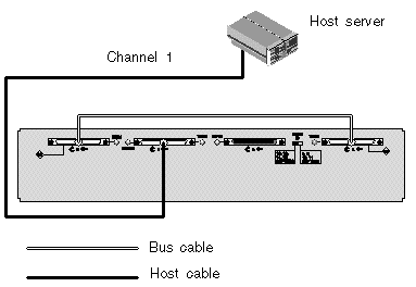
In FIGURE 4-9, the host server is connected to port B Out. The following table shows the drive IDs for FIGURE 4-9.
To connect multiple JBODs in a single-bus configuration to a single host, connect the following ports:
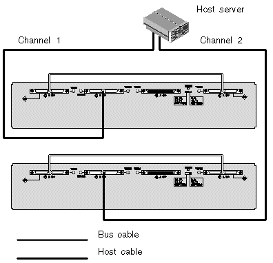
In FIGURE 4-10, the host server is connected to port B Out. The following table shows the drive IDs for FIGURE 4-10.
A dual-host, single-bus multi-initiator configuration primarily works in conjunction with multi-initiator software such as Sun Cluster or Veritas Cluster. In this configuration, each host server is connected to each host channel. Without the multi-initiator software, the host servers can write to the same drive simultaneously which might overwrite data.
You can configure a non-cluster dual-host, single-bus environment, but you must ensure that the hosts write to different disks on the SCSI bus by setting up a special configuration. For instance, you can specifically configure which host writes to each disk to prevent data overwrites.
|
Note - Each device in your configuration must have a unique ID, including any HBA devices. For instance, if your HBA device uses ID 6, do not use the left-switch setting, which sets the SAF-TE ID to 6. For details on setting the HBA device ID, see Section 5.6, Enabling VERITAS DMP in a Single-Bus Configuration. |

|
Caution - BEFORE you disconnect a cable from the array, the host bus on that cable must be inactive. |

|
Caution - When you connect the host cable in single-bus configuration, attach the host cable in a way that does not bend or damage the jumper cable. |
To connect a JBOD in a single-bus configuration to dual hosts, connect the following ports:
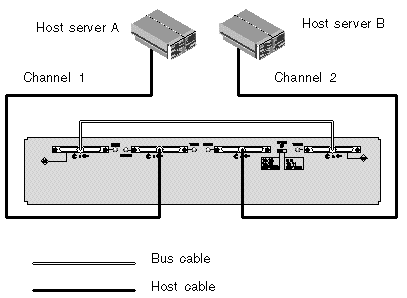
In FIGURE 4-11, Host A is connected to port B Out and Host B is connected to port A In. The following table shows the drive IDs for FIGURE 4-11.
There are two important features to note with the split-bus, single-initiator mode JBOD configuration:
Single-initiator mode is when there is only one host connection on a SCSI channel.

|
Caution - BEFORE you disconnect a cable from the array, the host bus on that cable must be inactive. |
FIGURE 4-12 shows a split-bus JBOD with two host connections, one host connection to each channel (single-initiator mode). This is an efficient way to provide mirroring capability for a single host.
|
Note - You can connect the cables to the inboard or outboard ports on a JBOD. Both configurations work. FIGURE 4-12 shows the cables connected to the outboard ports. |
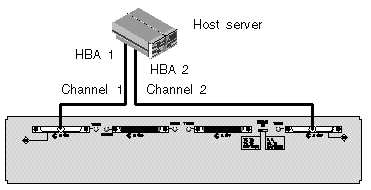
In FIGURE 4-12, HBA 1 is connected to port B In and HBA 2 is connected to port A Out. The following table shows the drive IDs for FIGURE 4-12.
FIGURE 4-13 shows multiple hosts with multiple JBODs in a split-bus JBOD configuration with two host connections, one host connection to each channel (single-initiator mode). This is an efficient way to provide mirroring capability.
|
Note - You can connect the cables to the inboard or outboard ports on a JBOD. Both configurations work. FIGURE 4-13 shows the cables connected to the outboard ports on the upper JBOD and the cables connected to the inboard ports on the lower JBOD. |
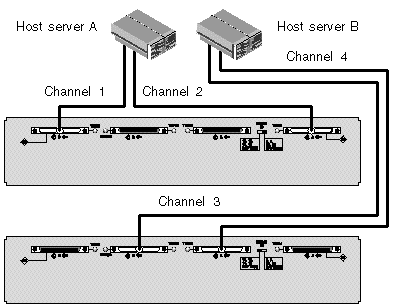
In FIGURE 4-13, Host A is connected to port B In and port A Out, and Host B is connected to port B Out and port A In. The following table shows the drive IDs for FIGURE 4-13.
To connect a split-bus JBOD, perform the following steps.
1. Connect each JBOD port to a host as shown in FIGURE 4-13.
2. Make inactive the host bus connections of any cable which will be installed or removed.
3. Use your host system disk management utilities to prepare the disks in the Sun StorEdge 3120 SCSI array for use.
Refer to your host system documentation for more information about disk management utilities available to you.
A dual-host, split-bus, multi-initiator configuration primarily works in conjunction with multi-initiator software such as Sun Cluster or Veritas Cluster. In this configuration, each host server is connected to two host channels. Without the multi-initiator software, the host servers can write to the same drive simultaneously which might overwrite data.
You can configure a non-cluster dual-host, split-bus, multi-initiator environment, but you must ensure that the hosts write to different disks on the SCSI bus by setting up a special configuration. For instance, you can specifically configure which host writes to each disk to prevent data overwrites.

|
Caution - BEFORE you disconnect a cable from the array, the host bus on that cable must be inactive. |
To connect a JBOD in a split-bus configuration to two hosts, connect the following ports:
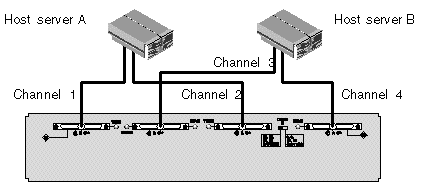
In FIGURE 4-14, Host A is connected to port B In and to port A In. Host B is connected to port B Out and to port A Out. This configuration is common for failover protection in a network cluster environment.
The following table shows the drive IDs for FIGURE 4-14.
Power on the equipment in the following order so the host computer discovers all connected arrays:
|
Note - For details on powering off the array, see Section 8.3, Powering Off the Array. |
Copyright © 2007, Dot Hill Systems Corporation. All rights reserved.