| C H A P T E R 8 |
|
Installing FRUs |
This chapter provides instructions for removing and installing field-replaceable units (FRUs) in Sun StorEdge 3120 SCSI arrays. FRU components can be replaced by customers or by Sun service representatives.
This chapter covers the following topics:
|
Note - Be sure to follow Section 8.2, Static Electricity and Other Precautions for all procedures. |
Most FRUs are hot-swappable. Hot-swappable means that a live upgrade can be performed - the FRU can be removed and replaced while the RAID array is powered on and operational.

|
Caution - Follow the FRU procedures carefully to ensure successful FRU replacement. |
Check that you received all field-replaceable units (FRUs) ordered with your Sun StorEdge 3120 SCSI array. For additional FRUs, consult your sales representative. For instructions on how to install or replace FRUs, review the following procedures or the Sun StorEdge 3000 Family Rack Installation Guide for 1U Arrays located on the product web site.
For a list of the FRU part numbers, refer to the Sun StorEdge 3000 Family FRU Installation Guide.
Follow these steps to prevent damaging the FRUs:

|
Caution - To prevent any possibility of data loss, back up the data prior to removing disk drives. |
Almost all FRU procedures are hot-swappable except for the chassis replacement procedure. However, you might need to power off the array (both power supplies) if you relocate the array or perform certain maintenance procedures with its associated servers.
Before you power off both power supplies, you must perform the following steps.
1. Stop all I/O activity to the array.
2. Power off both power supply/fan modules.
|
Note - For details on powering on the array, see Section 4.7, Power-On Sequence. |
This section provides instructions for removing and installing disk drive and air management sled FRUs, and covers the following topics:
To replace a disk drive, you first remove the defective disk drive and then install a replacement drive. The drive module is hot-swappable; it is replaced while the array is powered on.
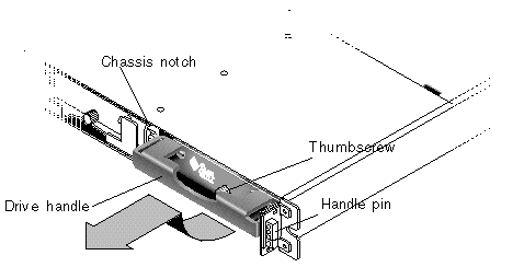
Before replacing a disk drive, perform the following steps to ensure that you have identified the correct defective disk for removal.

|
Caution - To prevent any possibility of data loss, back up data prior to removing disk drives. |
1. Examine the back of the array, and record the cable connections.
2. Physically locate the defective disk drive.
An amber LED next to a drive on the front panel of the JBOD indicates a failed disk drive. For details, see Section 6.2, Front-Panel LEDs.
3. Record the Chl and ID number for the defective disk drive (for example, Chl 0 ID 4).
For descriptions of ID settings, see Section 4.6.2, Fixed Drive IDs.
4. (Optional.) In Sun StorEdge Configuration Service, a red icon  in the main window indicates a JBOD drive failure. Review the error log to confirm the disk drive ID for the failed drive.
For details on the Sun StorEdge Configuration Service main window, see Section 5.2, Monitoring with Sun StorEdge Configuration Service.
5. (Optional.) In Sun StorEdge CLI, run the show enclosure-status command. If the drive status is "Absent" the drive may have failed, or has been removed from the chassis.
For details on the show enclosure-status command, see Section 5.4, Monitoring with the Sun StorEdge CLI.

|
Caution - Failure to identify the correct disk drive may result in replacing the wrong disk drive and could cause a loss of data. Be sure that you have identified the correct disk drive. An amber drive LED indicates a drive failure. For details, see Section 6.2, Front-Panel LEDs. |

|
Caution - To prevent any possibility of data loss, back up the data prior to removing disk drives. |
Remove the defective disk drive with the following steps.
1. Unlock the locks with the provided key, and gently pull the plastic front bezel away from the front of the unit so that it drops down and is supported by the two hinged brackets on the sides.
2. Turn the thumbscrew counterclockwise several full turns until the thumbscrew and drive module are loosened.
3. Gently pull the release handle upward.
4. Pull the drive module out until the drive connector has fully disconnected from the midplane.
5. Wait 20 seconds for the drive to stop spinning and then remove it from the chassis.
To install the replacement disk drive, perform the following steps.
1. Gently slide the drive module into the drive slot until the handle pins slip into the chassis notch.
2. Lower the disk drive handle until it is vertical.
3. Press and hold the drive handle in while you press the thumbscrew in until it engages the threads.
4. Turn the thumbscrew clockwise until it is finger-tight.
|
Note - To ensure that a thumbscrew is finger-tight, tighten it with a screwdriver and then loosen the thumbscrew counterclockwise a quarter turn. |
5. Push the plastic front bezel onto the front of the unit until it is seated firmly, and use the key to lock the locks.
A green drive LED indicates a functional drive. For details, see Section 6.2, Front-Panel LEDs.
6. Perform any operations your host software requires to discover the new drive and bring it under software control.
For specific operating system instructions, see .
7. (Optional.) If you are using Sun StorEdge Configuration Service, you can discover the new drives using the software.
For instructions, refer to the Sun StorEdge 3000 Family Configuration Service User's Guide.
An air management sled looks identical to the disk drive module; however, it is an empty box and is used to maintain optimum airflow in a chassis.
If you have removed a disk drive and do not replace it, you can insert an air management sled to maintain the optimum airflow inside the chassis. You can install the air management sled by using the same procedure as Section 8.4.1.3, Installing a New Disk Drive.
Topics covered in this section are:
The following power specifications apply to the power supply and fan modules:

|
Caution - To avoid damage to equipment, do not remove a power supply/fan module without a working replacement. |
1. Be sure to follow Section 8.2, Static Electricity and Other Precautions.
2. Turn off the power, and then remove the AC cord locks (if applicable) and the power cable.
3. Turn the thumbscrew at the top of the power supply latch counterclockwise until the thumbscrew is disengaged from the power supply.
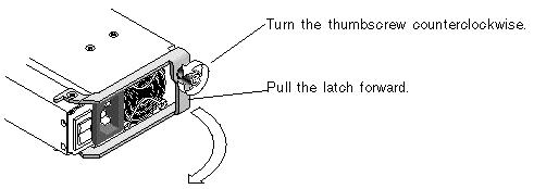
4. Pull the latch forward about 90 degrees to disconnect the power supply/fan module from the midplane.
5. Pull the power supply/fan module out of the chassis.
1. Slide the new module into the fan and power supply slot.
2. Push the latch back so that the power supply is fully inserted into the chassis.
3. Turn the thumbscrew at the top of the power supply latch clockwise until it is finger-tight, to secure the module.
|
Note - To ensure that a thumbscrew is finger-tight, tighten it with a screwdriver and then loosen the thumbscrew counterclockwise a quarter-turn. |
4. Attach the power cable and reinstall the AC cord locks if applicable.

|
Caution - To avoid damage to equipment, do not remove a power supply/fan module without a working replacement. |
1. Be sure to follow Section 8.2, Static Electricity and Other Precautions.
2. Turn off the power and remove the power cable.
3. Turn the thumbscrew at the top of the power supply latch counterclockwise until the thumbscrew is disengaged from the power supply.
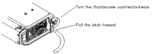
4. Pull the latch forward about 90 degrees to disconnect the power supply/fan module from the midplane.
5. Pull the power supply/fan module out of the chassis.
1. Slide the new module into the fan and power supply slot.
2. Push the latch back so that the power supply is fully inserted into the chassis.
3. Turn the thumbscrew at the top of the power supply latch clockwise until it is finger-tight, to secure the module.
|
Note - To ensure that a thumbscrew is finger-tight, tighten it with a screwdriver and then loosen the thumbscrew counterclockwise a quarter-turn. |
4. Connect the DC power cable to the DC source.
Check the DC cable part number and wire labels carefully before connecting the cable to the source (see the table below). GND = Chassis Ground.
5. Extend the length of the DC power cable as needed, strip the last 1/4-inch of the cable, insert it into a provided Panduit tube, and crimp the tube.
6. Attach the power cable to the array.
Replacing and installing LED modules includes the following steps:
|
Note - Be sure to follow Section 8.2, Static Electricity and Other Precautions for all procedures. |
The following parts are included in the LED module replacement kit:
The following tools are required to complete this procedure:
To remove the front bezel and right ear cap to replace or install an LED module, perform the following steps.
1. Power off both power supply modules on the array.
2. If attached, unlock the front bezel cover with the provided key.
3. Grasp the front bezel cover on both sides and pull it forward and then down.
4. Press the right bezel arm (hinge) toward the left side to release it from the chassis hole.
The left bezel arm also disengages.
5. Note the location of the chassis bezel holes on each ear.
6. Remove the plastic cap from the right ear of the array.
a. Squeeze both sides of the cap at the top and the bottom.
b. Turn the cap toward the center of the array until it disengages and pull it free.
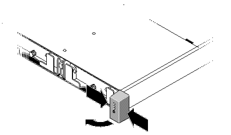
To remove the LED module, perform the following steps.
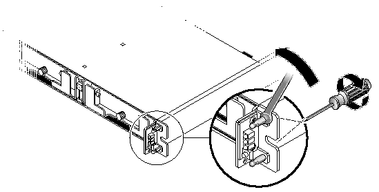
1. Remove the ball studs holding the LED module to the chassis.
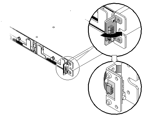
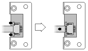
2. Unfold the ribbon cable and detach it from the LED module by pulling out the small cable lock drawer and sliding the LED module free.
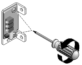
3. Remove the two panhead screws holding the LED module to the bracket.
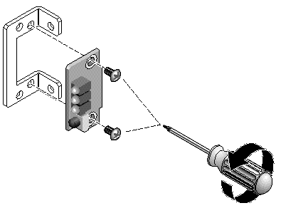
To install a new LED module, perform the following steps.
1. Attach the new LED module to the bracket using the two screws from Step 3 in Section 8.6.3, Removing the LED Module.
2. Pull out the cable lock drawer on the new LED module.
3. Insert the ribbon cable into the new LED module and close the cable lock drawer to reconnect the cable to the LED module.
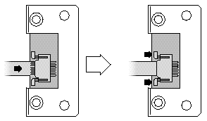
|
Note - The blue side of the ribbon cable must face towards the LED module and the ribbon contact area must be completely inserted into the LED module before the lock drawer is closed. |
4. Fold the ribbon to lay flat against the back of the LED module and attach the LED module to the chassis with the ball studs from Step 1 in Section 8.6.3, Removing the LED Module.
5. If the ball studs were attached to flathead screws, reattach these screws through the bracket to the ball studs.
Replacement screws are provided in the ship kit in case the original screws were damaged during removal.
6. If it was removed, restore the chassis to its rack.
To replace the ear cap and the front bezel, perform the following steps.
1. Push the top and bottom of the ear cap onto the ear, pressing in on the top side toward the center of the array until the ear cap snaps into place.
2. Insert the bezel arms into the chassis holes.
3. Lift the bezel into position and press it onto the front of the chassis until it is flush with the front.
4. Lock the bezel in the closed position with the keys.
5. Remove the keys if they were not initially inserted into the chassis.
6. Power on both power supply modules.
The Sun StorEdge 3120 SCSI array box FRU includes a chassis, its drive midplane, and its backplane. This product is ordered to replace a box that has been damaged or whose midplane, backplane, or terminator module has been damaged.
To make a fully functional array, you must add the following parts from the replaced array:
To install the individual modules, use the replacement instructions provided in this guide.
To configure the array, see Chapter 4.
To replace the chassis frame of an existing JBOD, perform the following steps.

|
Caution - Connected hosts must be inactive during this replacement procedure. |
|
Note - Be sure to follow Section 8.2, Static Electricity and Other Precautions. |
1. Power off both power supply modules on the defective array.
2. Ensure all SCSI cables attached to the I/O module are labeled clearly.
3. Write down the defective array's cabling configuration.
4. Write down the SCSI ID switch setting, right or left.
The IDs assigned for disks 1 through 4 depend on the switch settings on the array. The right switch setting uses IDs 8, 9, 10, and 11. The left switch setting uses IDs 12, 13, 14, and 15.
5. Remove all SCSI cables attached to the I/O module.
6. Label each disk drive with its disk slot position in the array.
7. Remove the power supply modules and disk drives from the defective array.
8. Remove the defective chassis.
9. Obtain the replacement chassis.
10. Re-install all previously removed modules in their original positions into the replacement array.
11. Re-install all SCSI and power cables in their original positions.
12. Set the SCSI ID switch to right or left depending on your previous configuration.
|
Note - SCSI IDs are set based on the switch setting on the array when it is powered on. If you change the switch setting, the SCSI IDs will change after you power off, and then power on. |
13. Power on both power supply modules.
14. See Chapter 4 for instructions about configuring the JBOD.
Copyright © 2007, Dot Hill Systems Corporation. All rights reserved.