| C H A P T E R 2 |
|
Installing the Appliance and Back-End Storage |
This chapter describes the process of installing the Sun StorageTek 5220 NAS Appliance, a controller unit, and expansion units. It contains the following sections:
The installation procedures in this chapter require the following items:
The Sun StorageTek 5220 NAS Appliance can be installed in the Sun Rack 900, the Sun
 Rack 1000, or third-party racks that comply with the requirements. Although the system is installed in a single cabinet or rack, the appliance and the back-end storage units require different rails to support them.
|
Note - A cabinet is a rack with a door and the two terms are used interchangeably. |
Requirements to support installation of the storage system:
Rack density varies widely based on systems installed, power distribution installation (in-cabinet, external), power source (single-phase, three-phase), and whether redundant power is required. Some rack vendors do not support a fully-loaded rack because of the amount of power required. For power specifications, refer to Appendix A.
|
Note - Not all third-party racks are compatible with these slide rail kits. |
The Sun StorageTek 5220 NAS Appliance is supported with the slide rail kit (370-7669-02) and cable management arm (370-7668-02). The slide rail kit contains four-point mounted slide rails and is designed to enable the Sun StorageTek 5220 NAS Appliance to be installed in the Sun Rack 900, the Sun Rack 1000, and other ANSI/EIA 310-D-1992 or IEC 60927 compliant racks. No other kits are available to allow two-point, front-mount, or mid-mount installation.
The slide kit includes hardware that enables mounting to any of the following types of rails:
Use the universal rail kit to mount the controller and expansion units in any standard Sun cabinet, such as the Sun Rack 900/1000 cabinet.
Use the following procedures to prepare for installation:
|
Note - The rack must have an AC power disconnect. This power source disconnect must be easily accessible, and it must be labeled as controlling power to the entire rack, not only to the appliance |
Be sure the location of the cabinet or rack complies with the following requirements and that it has been installed as described in its installation instructions:
Before you begin mounting the rail kits, do the following:
1. Stabilize the cabinet as described in the cabinet documentation.
2. If the cabinet has casters, make sure the casters are locked to prevent the cabinet from rolling.
3. Remove or open the front panel.
4. Remove or open the vented back panel.
You must maintain reliable grounding of this equipment. Review specifications in Appendix A to determine the appropriate AC branch circuit size for the quantity of units in your configuration and your operating voltage. Always follow your local electrical codes for loading circuits.

|
Caution - Do not power on any units until after you have connected the Sun StorageTek 5220 NAS Appliance to the network. |
The safe ground conductor provides proper grounding only for the Sun StorageTek 5220 NAS Appliance. You must provide additional proper grounding for the rack and other devices installed in it.
Review specifications in Appendix A to determine isolation and continuous power requirements.
When you unpack the shipping box, verify that you have all of the parts:
When you unpack the shipping box, verify that you have all the parts:
|
Assemble main and extender sections of left and right rails (Typically, left and right rails are shipped pre-assembled) |
||
When you unpack the shipping box, verify that you have all of the parts:
Make sure you have the two power cords for your location, shipped separately.
When you unpack the shipping box, verify that you have all of the parts.
The power cords are shipped separately.
At a minimum, the system has an appliance and the controller unit. Your system can have one or two expansion units, installed now or at a later date. Plan the placement of the rails carefully because they are spaced differently, depending on whether you are installing a unit or an appliance.
In general, the installation is accomplished in the following order:
1. Install the universal slide rail kit for the controller unit, starting at the bottom of the rack.
2. Install the universal slide rail kit for each expansion unit, starting above the controller unit.
3. Mount the controller unit at the bottom of the cabinet.
4. Mount each expansion unit, from the bottom up.
5. Install the slide rails for the appliance.
6. Install the cable management kit.
FIGURE 2-1 shows the cabinet with a controller unit, an expansion unit, an additional expansion unit, and an appliance.
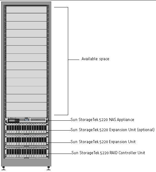
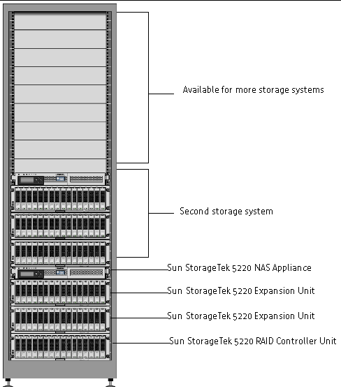
FIGURE 2-2 shows a cabinet with two complete but separate storage systems.
This procedure describes the steps to attach the universal rail kit to all standard Sun cabinets.
|
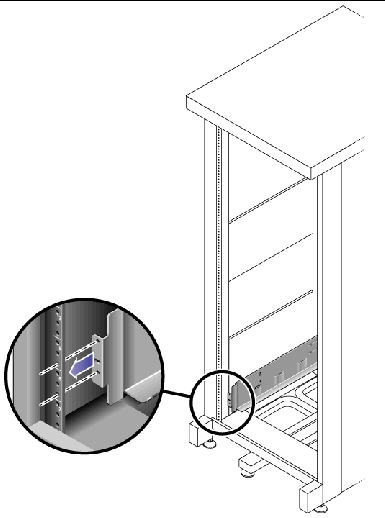
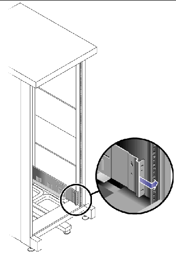
1. Position the front of the left rail behind the left front cabinet rail (FIGURE 2-3).
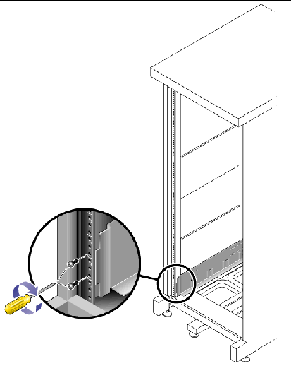
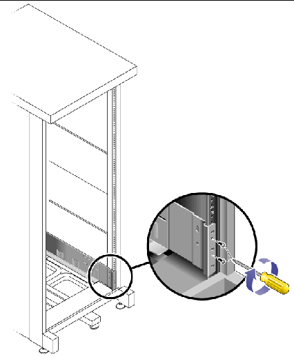
2. Use the No. 2 Phillips screwdriver to insert and tighten two 8-32 screws to secure the left rail to the front of the cabinet (FIGURE 2-4).
Each controller and expansion unit requires three standard mounting units (3U) of vertical space in the cabinet. Each standard mounting unit (U) has three mounting holes in the left and right cabinet rails. Insert the screws into the lowest holes in the top two mounting units of the 3U slot in which the tray is to be mounted.
These screws pass through the cabinet rail holes and screw into threaded holes in the left rail.
3. Repeat Step 1 and Step 2 for the right rail.
4. At the back of the cabinet, adjust the length of the left rail as needed to fit the cabinet, and position the rail flange over the face of the cabinet rail (FIGURE 2-5).
5. Align the rail flange so that the mounting holes correspond to those at the front of the cabinet.
6. Use the No. 3 Phillips screwdriver to insert and tighten four metric M6 screws (two per side) at the back of the rail (FIGURE 2-6).
7. Repeat Step 4, Step 5, and Step 6 for the right rail.
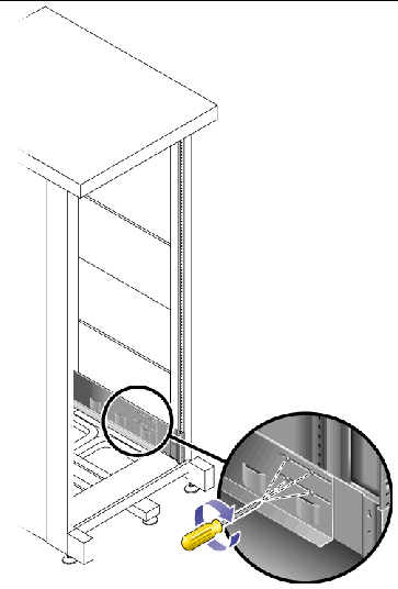
8. Using the No. 2 Phillips screwdriver, tighten the eight adjustment screws (four on each side) toward the back of each rail (FIGURE 2-7).
Install the controller unit in the first empty 3U slot at the bottom of the cabinet. Install expansion units above the controller unit, from the bottom upward.
|
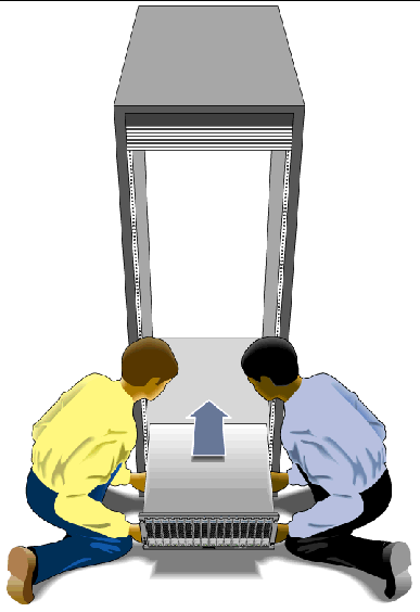
1. Using two people, one at each side of the unit, carefully lift and rest the unit on the bottom ledge of the left and right rails (FIGURE 2-8).

|
Caution - Use care to avoid injury. A unit can weigh up to 95 pounds (45 kg). |
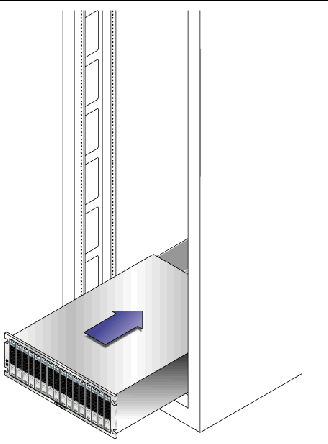
2. Slide the unit carefully into the cabinet until the front flanges of the unit touch the vertical face of the cabinet (FIGURE 2-9).
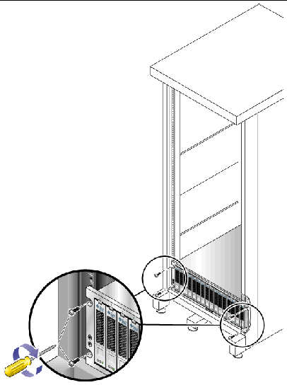
3. Use the No. 3 Phillips screwdriver to install and tighten four M6 screws (two per side) to secure the tray to the front of the cabinet (FIGURE 2-10).
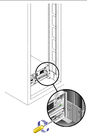
4. Install and tighten two 6-32 screws (one per side) at the back of the unit, to secure the back of the unit to the cabinet (FIGURE 2-11).
|
Note - The two upper holes on the back of the unit are not used. |
Installing a appliance takes three step:
2. To Install the Cable Management Kit
3. To Verify the Operation of the Slide Rails and the CMA
1. Pull both mounting brackets completely out of their respective slide rails:
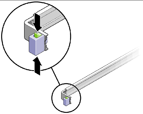
a. Press and hold simultaneously the upper and lower lock buttons of the slide rail lock (FIGURE 2-12).
b. Pull the mounting bracket out until it locks in the extended position.
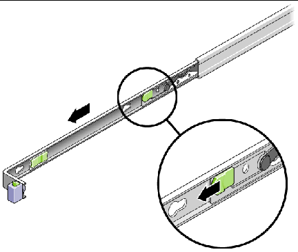
c. Slide the mounting bracket release button in the direction shown in FIGURE 2-13, and then slide the mounting bracket out of the slide rail.
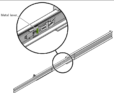
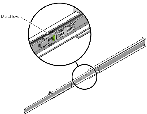
d. Press the metal lever labeled Push on the middle section (FIGURE 2-14) of the sliding rail, and then push the middle section back into the rack.
2. Attach a mounting bracket to the right side of the appliance chassis.
a. Position the mounting bracket against the appliance chassis (FIGURE 2-15) so that the bracket's slide rail lock is at the front and its three keyed openings align with the three locating pins on the side of the chassis.
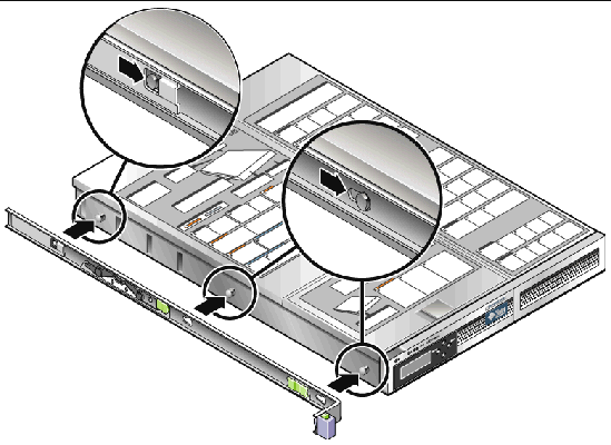
b. With the three pins protruding though the openings in the mounting bracket, pull the bracket toward the front of the chassis until it locks into place with an audible click.
c. Verify that the three pins are trapped in their openings and that the back pin has engaged the mounting bracket lock, as shown in FIGURE 2-15.
3. Attach the second mounting bracket to the left side of the appliance chassis.
4. On the rack posts, determine which hole numbers to use for the slide rails. The appliance requires one rack unit (1U).
5. Determine which screws to use to mount the slide rails.
6. Attach a slide rail to the right front rack post.
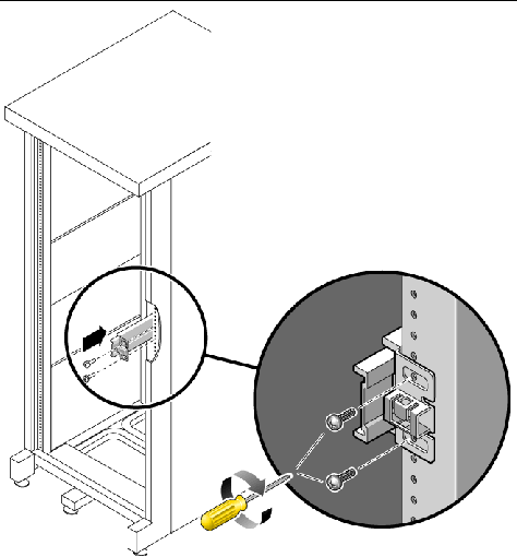
a. Attach the front of a slide rail to the right front rack post (FIGURE 2-16) using two screws. Do not tighten the screws yet.
b. Adjust the length of the slide rail by sliding the back mounting flange to reach the outside edge of the back rack post.
c. Use two screws to attach the back of the slide rail to the back rack post loosely.
7. In the same way, attach the second slide rail to the left rack posts. Do not tighten the screws.
8. Use the slide rail spacing tool to adjust the distance between the slide rails:
a. At the front of the rack, insert the left side of the tool into slots at the end of the left rail (FIGURE 2-17).
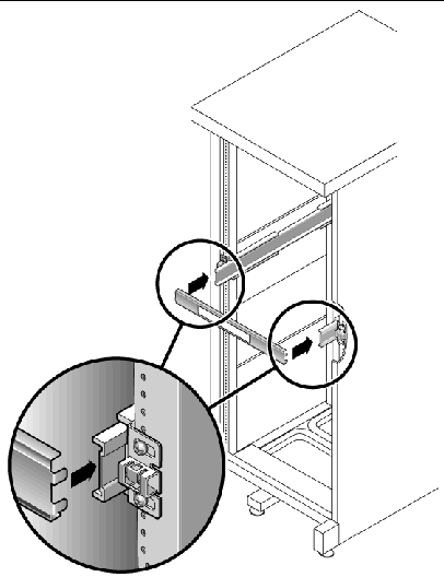
b. Insert the right side of the tool into the front end of the right rail, while sliding the end of the rail to the right or left as needed to allow the ends of the tool to enter the ends of both rails. The distance between the rails is now equal to the width of the appliance with its mounting brackets.
c. Tighten the screws to lock the ends of the rails in place.
d. At the back of the rack, repeat Step a through Step c for the back ends of the rails.
9. Deploy the anti-tilt bar, if the chassis or rack is so equipped.

|
Caution - The weight of the appliance on extended slide rails can be enough to overturn a cabinet. |
10. With a partner, lift the appliance and insert the ends of its mounting brackets into the sliding rails (FIGURE 2-18).

|
Caution - The appliance weighs approximately 52 pounds (24 kg). Two people are required to lift and mount the system into a cabinet. |
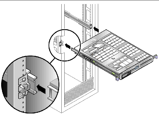
11. Simultaneously release the rail locks on each side of the sliding rails, and guide the chassis into the rack.

|
Caution - Verify that the appliance is securely mounted in the rack, and that the slide rails are locked to the mounting brackets. |
The.cable management assembly (CMA) clips into the ends of the left and right sliding rail. No screws are necessary for mounting the CMA.

|
Caution - Support the CMA during this installation. Do not allow the assembly to hang by its own weight until it is secured by all three attachment points. |
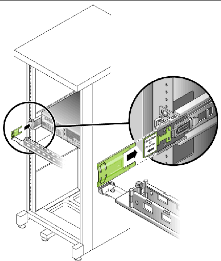
1. At the back of the rack, plug the CMA rail extension into the end of the left sliding rail assembly (FIGURE 2-19).
The tab at the front of the rail extension clicks into place.
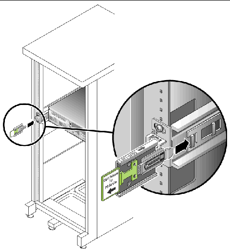
The right sides of the two CMA arms have hinged extensions. On the manufacturer's instruction sheet, the smaller extension is called the CMA Connector for Inner Member. It attaches to the right mounting bracket. The larger extension is called the CMA Connector for Outer Member, and attaches to the right sliding rail.
2. Insert the smaller extension into the clip located at the end of the mounting bracket (FIGURE 2-20).
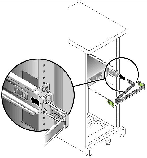
3. Insert the larger extension into the end of the right sliding rail (FIGURE 2-21).
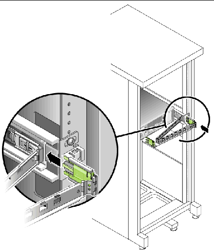
4. Insert the hinged plastic connector at the left side of the CMA fully into the CMA rail extension (FIGURE 2-22).
The plastic tab on the CMA rail extension locks the hinged plastic connector in place.
|
Tip - Two people are needed for this procedure: one to move the appliance and one to observe the cables and CMA. |
1. Deploy the cabinet's anti-tilt bar, if it has one.
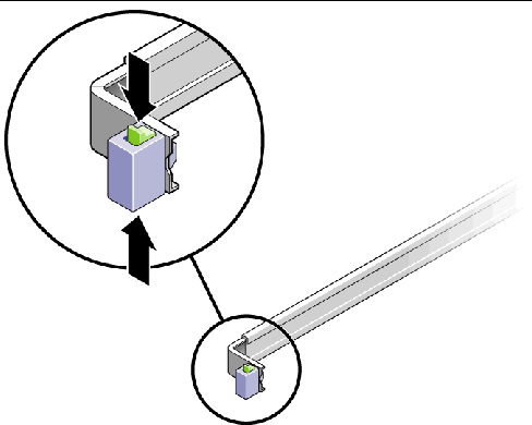
2. Unlock the slide lock buttons (FIGURE 2-23) at the right and left sides of the appliance chassis, and slowly pull the appliance out of the rack until the slide rails reach their stops.
3. Inspect the attached cables for any binding or kinks.
4. Verify that the CMA extends fully and does not bind in the slide rails.
5. When the appliance is fully extended, release the slide rail lever stops (FIGURE 2-24).
Push both levers simultaneously and slide the appliance back into the rack.
6. Simultaneously unlock both slide rail release buttons (FIGURE 2-25), and push the appliance completely into the rack.
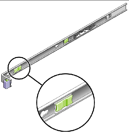
The appliance stops after approximately 15 inches (40 cm) of travel.
7. Verify that the cables and the CMA retracted without binding.
8. Adjust the cable hangers and CMA as required
This section describes how to connect the power cables.
|
Note - Do not power on the units until you complete the installation procedures for your system. The power-on sequence is described in detail in Powering On the System. |
|
1. Verify that both power switches are off for each controller unit and expansion unit in the cabinet. The toggle switch must be set to 0.
2. Connect each power supply in each unit to a separate power source in the cabinet.

|
Caution - The cabinet must have two power sources connected to two separate power circuits. |
3. Connect each power supply in the Sun StorageTek 5220 NAS Appliance to a separate power source in the cabinet.
As soon as you connect the appliance's power cords to the cabinet, the AC LE D on the front lights, indicating standby power mode.
4. Connect the primary power cables from the cabinet to the external power source.
When you have installed the appliance and its units and have connected their power cables, you are ready to connect the appliance to the controller unit and connect the controller unit to any expansion units, as described in Chapter 3.
Copyright © 2006, Sun Microsystems, Inc. All Rights Reserved.