| Sun Storage J4200/J4400 Array Hardware Installation Guide |
| C H A P T E R 1 |
|
The Sun Storage J4200/J4400 Array |
The Sun Storage J4200 and J4400 arrays are general purpose, high-availability, and cost-effective serial attached SCSI (SAS) devices. The J4200 is a 2U, 12-disk tray and the J4400 is a 4U, 24-disk tray. Each supports SAS and Serial Advanced Technology Architecture (SATA) disk drives. The main components in each array are hot-swappable, including the SAS Interface Module (SIM) boards and drives, and the dual load-sharing power supplies and fans, providing a fault-tolerant environment with no single point of failure.
The J4200/J4400 arrays support 15K SAS drives and 7.2K SATA II drives. You can interconnect up to four J4200/J4400 trays, with up to 48 drives in interconnected J4200s and up to 96 drives in interconnected J4400s, all of which are designed to fit into a standard 19-inch cabinet. This renders a raw storage capacity of 14.4 TB for SAS disks (300 GB per disk) or 36 TB for SATA II disks (750 GB per disk) for the J4200, and 28.8 TB for SAS disks (300 GB per disk) or 72 TB for SATA II disks (750 GB per disk) for the J4400. Refer to the Sun Storage J4200/J4400 Array Release Notes (820-3222-nn) for a complete listing of supported drives.
The J4200/J4400 is available for Solaris, Linux, Windows, and VMware operating systems. You manage the array with the Sun StorageTek Common Array Manager (CAM) software.
The trays can be installed into the following cabinets:
The J4200/J4400 array can be delivered fully assembled or packaged as individually ordered components that you install into the chassis. Customer-Replaceable Units provides a list of these components. All CRUs have a document describing installation instructions.
FIGURE 1-1 shows the Sun Storage J4200 SAS connection to a data and management host.
FIGURE 1-1 J4200 Array Connected to a Data and Management Host
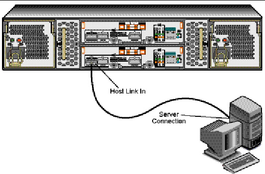
FIGURE 1-2 shows the Sun Storage J4400 SAS connection to a data and management host.
FIGURE 1-2 J4400 Array Connected to a Data and Management Host
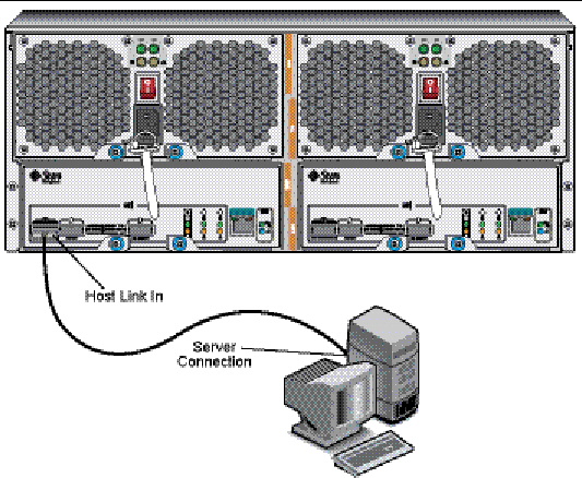
FIGURE 1-3shows a Sun Storage J4200 interconnected with other J4200 arrays.
FIGURE 1-3 J4200 Array Interconnected With Three Additional J4200s

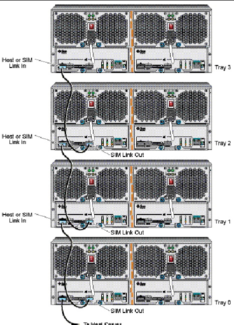
FIGURE 1-4 shows a Sun Storage J4400 interconnected with other J4400 Arrays.
FIGURE 1-4 J4400 Array Interconnected With Three Additional J4400s
Following is a list of the current Sun Storage J4200 Array shipping kit contents. In case of any changes, refer to the Sun Storage J4200/J4400 Array Release Notes (820-3222-nn) for the latest list:
Following is a list of the current Sun Storage J4400 Array shipping kit contents. In case of any changes, refer to the Sun Storage J4200/J4400 Array Release Notes (820-3222-nn) for the latest list:
Check the Rail Kit Contents describes the rail kit contents.
This section provides information on the Sun Storage J4200/J4400 array hardware.
This product is intended for restricted access areas whereby access is controlled through the use of a means of security (e.g., key, lock, tool, badge access), and personnel authorized for access have been instructed on the reasons for the restrictions and any precautions that need to be taken.

|
Caution - Only trained service personnel should remove the covers on this equipment. |
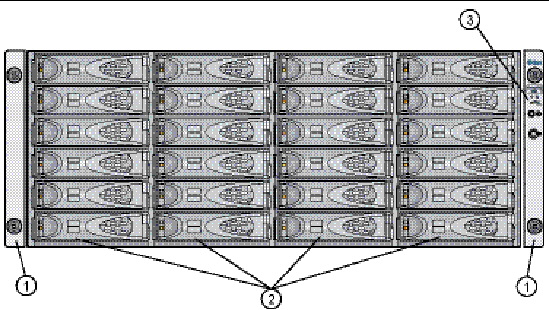
Components that are accessed from the front (see FIGURE 1-5 for the J4200 and FIGURE 1-6 for the J4400) of the Sun Storage J4200/J4400 include the following:
FIGURE 1-5 J4200 Array Front Access Components
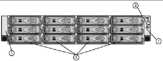
FIGURE 1-6 J4400 Array Front Access Components
|
End caps with serial number (left) and status indicators (right) |
|
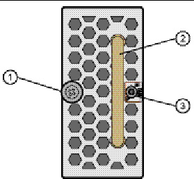
Two indicators on the front of the Sun Storage J4200/J4400 are located on the right-side end cap of the tray (FIGURE 1-7).
FIGURE 1-7 Indicators on the Front of a Sample J4200 Array
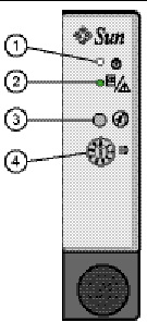
Following are the J4200/J4400 Array front panel status indicator descriptions.
Following are descriptions for the Audible Alarm Silence Button and the System ID:
|
When the alarm is sounding, press this button to silence the enclosure’s audible alarm. |
||
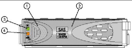
Disk drives for the Sun Storage J4200/J4400 array have several components: a hard disk, a hard disk carrier, the disk-release button, the disk ejector handle, and two status indicators (see FIGURE 1-8). You can access the disk drives from the front of the trays. The J4200/J4400 supports SAS disk drives or SATA II disk drives. A label on the handle indicates the drive type and its size and speed.
J4200s hold up to 12 disk drives, and four trays can be interconnected for a maximum of 48 disk drives in a chain; J4400s hold up to 24 disk drives, and four trays can be interconnected for a maximum of 96 disk drives in a chain. You must have at least two drives in either array.
Twelve or 24 removable disk drives are numbered from left to right, labeled from 0 on the lower left to 11 (J4200) or 48 (J4400) on the upper right.
FIGURE 1-8 shows the disk-release button, the disk handle, and the status indicators.
|
Release button, press towards the right - disengages the release handle |
|
Following are the J4200/J4400 disk drive status indicator descriptions.
Aside from a larger form factor, the J4200 and J4400 rear components are different. The J4200 has separate power supplies and fans, where the J4400 has an integrated power supply and fan module.
There are three mini-SAS connectors:
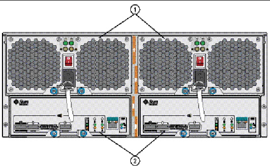
FIGURE 1-9 shows the J4200 Array rear-access components.
FIGURE 1-9 J4200 Array Rear-Access Components
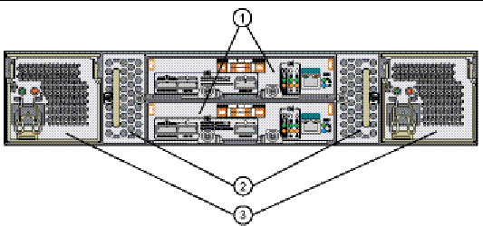
FIGURE 1-10 J4400 Array Rear-Access Components
The SIM board for each of the arrays includes the same components, indicators, and ports, however, the J4400 SIM board is larger than the J4200 SIM board, as required by the array’s form factor.
Each hot-swappable SIM board has one SAS inbound connector and two SAS outbound connectors, and one serial management port that is reserved for Sun Customer Support Personnel only.
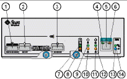
FIGURE 1-11 and FIGURE 1-12 call out the individual components on the back of the SIM board, and TABLE 1-3 provides descriptions of these components. TABLE 1-4 describes the SIM board component status indicators.
FIGURE 1-11 J4200 Array SIM Board Components and Status Indicator Descriptions
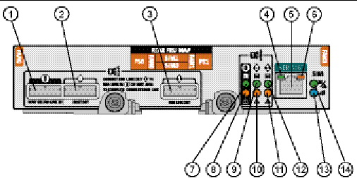
FIGURE 1-12 J4400 Array SIM Board Components and Status Indicator Descriptions
Following are the J4200/J4400 SIM board status indicator descriptions:
|
System is booting, being configured, or downloading firmware |
||||
The J4200 has separate power supplies and fans, where the J4400 has an integrated power supply and fan module.
Each tray contains two hot-swappable, redundant power supplies. If one power supply is turned off or malfunctions, the other power supply maintains electrical power to the tray.
|
|
Caution - The power supplies in this equipment can produce high energy hazards. Only instructed personnel with authorized access to this equipment can remove and replace modules in the system. |
FIGURE 1-13 shows J4200 array power supplies and FIGURE 1-14 shows J4400 array power supplies.
FIGURE 1-13 J4200 Array Power Supplies
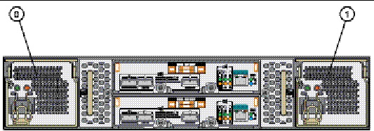
FIGURE 1-14 J4400 Array Power Supplies
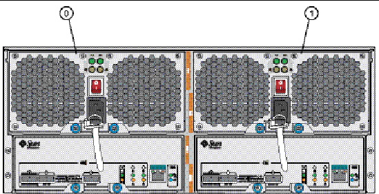
FIGURE 1-15 shows an individual J4200 array power supply and FIGURE 1-16 shows an individual J4400 array power supply.
FIGURE 1-15 Individual J4200 Power Supply
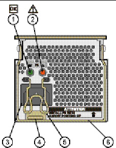
TABLE 1-5 describes the J4200 power supply components and TABLE 1-6 provides the J4200 power supply status indicator descriptions.
|
See TABLE 1-6. |
||
|
See TABLE 1-6. |
||
|
Used to remove the power supply from and insert the power supply into the J4200 enclosure. |
Following are the J4200 power supply status indicator descriptions.
FIGURE 1-16 Individual J4400 Power Supply
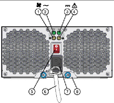
TABLE 1-7 describes the J4400 power supply components and TABLE 1-8 provides the J4400 power supply status indicator descriptions.
|
See TABLE 1-8. |
||
|
See TABLE 1-8. |
||
|
See TABLE 1-8. |
||
|
See TABLE 1-8. |
||
Following are the J4400 power supply status indicator descriptions.
The fans circulate air inside the tray by pulling it through the vents on the front of the assembly and pushing it out of the vents on the back of each fan.
Each J4200 array contains two hot-swappable fans for redundant cooling. Fan Module 0 is on the left and Fan Module 1 is on the right. If one of the fans fails, the remaining fan continues to provide sufficient cooling to operate the array. The remaining fan runs at a higher speed until the failed fan is replaced. Replace a failed fan as soon as possible.
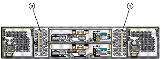
FIGURE 1-18 Individual J4200 Array Fan Module
Following are the J4200 fan status indicator descriptions.
The J4200/J4400 Array can be delivered fully assembled or packaged as individual components that you install into the chassis. All customer-replaceable units (CRUs) have a document describing the installation instructions in its shipping box. Additionally, the Common Array Manager (CAM) software has a Service Advisor application with wizards that guide you through CRU replacements.
The following hardware components are designed to be customer installable:
The Sun StorageTek Common Array Manager (CAM) software suite provides management, monitoring, and service capabilities. The software has both a browser interface and a command-line interface (CLI).
The J4200/J4400 array requires a minimum version of CAM of 6.1.1. For detailed information about which versions of CAM to use with the arrays, refer to the Sun Storage J4200/J4400 Array Release Notes, part number 820-3222-xx, which is available at the following location:
http://docs.sun.com/app/docs/prod/j4200.array
For complete CAM documentation, go to the following location:
http://docs.sun.com/app/docs/prod/stor.arrmgr
For more information about CAM, and to download the latest version, go to the following location:
http://www.sun.com/storagetek/management_software/resource_management/cam/
The full management software is installed on a management workstation. The management software communicates with the J4000 arrays via a proxy agent that is installed on the data host. It provides:
The remote proxy agent enables communication, equivalent to in-band management, from the full management host to the array over an out-of-band-band IP network.
If the proxy is enabled, the full install of the Common Array Manager can manage the J4000 Family array directly. To remotely use the browser interface to manage the J4000 Family array, you sign into the IP address of the full management host, sign into the software from the Java Web Console, and select the J4000 array. The remote proxy must be enabled while running the installation wizard or script.
The Sun StorageTek Common Array Manager software’s command-line interfaces provide the same control and monitoring capability as the Web browser and it is scriptable for running frequently performed tasks.
For more information about CLI commands, see:
http://docs.sun.com/app/docs/prod/stor.arrmgr
Before you begin to install the J4200/J4400 Array, you must first:
| Note - This product is intended to be used in restricted access locations, such as in dedicated equipment rooms or closets. |
The following checklist (TABLE 1-10) outlines of the tasks required for installing the Sun Storage J4200/J4400 Array hardware and tells you where to find detailed procedures. To ensure a successful installation, perform the tasks in the order in which they are presented.
|
Unpacking guide attached to the outside of the shipping carton |
||
|
Connecting to the Data and Management Host or Another J4200/J4400 Array |
||
| Sun Storage J4200/J4400 Array Hardware Installation Guide | 820-3218-14 |
© © 2009 Sun Microsystems, Inc. All rights reserved.