| C H A P T E R 4 |
 Mounting the Server Into a 2-Post Rack
 |
This chapter provides instructions for installing the server in an open 2-post rack.
| Note - The server ships with a 19-inch, 4-post hardmount rack kit. The rack rail kits described in this chapter must be ordered separately from Sun. |
This chapter contains the following sections:
| Note - References to left and right are from your viewpoint as you face either the front or rear of the equipment. |

|
Caution - The server is heavy. Two people are required to lift and mount the server into a rack enclosure when following the procedures in this chapter. |
The server ships with a 19-inch, 4-post hardmount rack kit (see Hardmounting the Server in a 19-Inch 4-Post Rack for installation instructions). TABLE 4-1 lists two additional 2-post rackmount kit options that can be ordered from Sun. This chapter provides installation instructions for these rackmount kit options.
| Note - If you have more than six DC-powered servers in the same rack, you might exceed Telcordia NEBS EMI limits. |
|
The hardmount kit for a 23-inch 2-post rack consists of:
| Note - The 23-inch 2-post rackmount kit supports rack web thicknesses (the width of the rack post) of 76.20 mm (3 in.), 101.6 mm (4 in.), and 127 mm (5 in.). |
FIGURE 4-1 Contents of the Hardmount 23-Inch 2-Post Kit
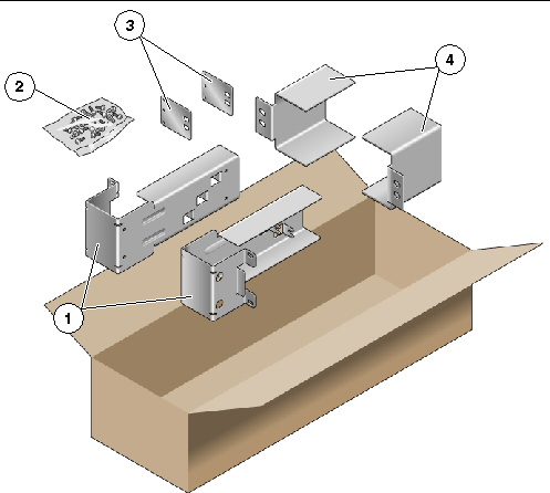
1. Get the side brackets from the rack kit (FIGURE 4-1).
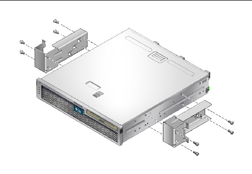
2. Using eight of the M5 × 7 SEM screws (four for each side bracket), secure the side brackets to the sides of the server (FIGURE 4-2).
FIGURE 4-2 Securing the Side Brackets to the Side of the Server
3. Get the rail guides from the rack kit (FIGURE 4-1).
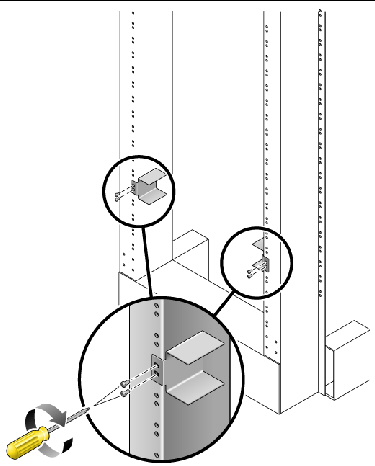
4. Lift the rail guides to the desired height in the rack and, using two screws each, secure both rail guides to the rack (FIGURE 4-3).
The size of the screws varies, depending on your particular rack.
FIGURE 4-3 Installing the Rail Guides in the Rack
5. Lift the server into the rack and slide it onto the rail guides (FIGURE 4-4).
FIGURE 4-4 Installing and Securing the Server in the 2-Post Rack
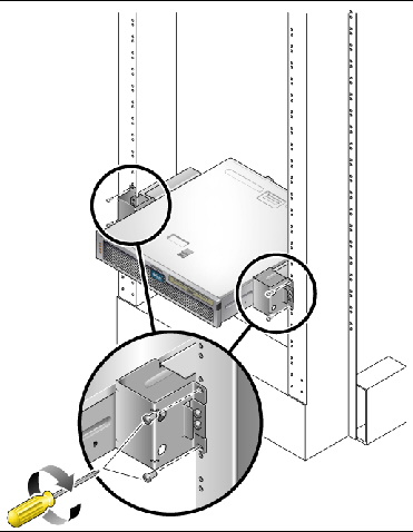
6. Using two screws on each side, secure each side bracket on the server to the front of the rack (FIGURE 4-4).
The size of the screws varies, depending on your particular rack.
7. (Optional) If your environment contains especially high vibrations, use the rear plates to further secure the server to the rack (FIGURE 4-1).
The rear plates attach to the rear of the post and to one of the three eyelets on each side bracket, depending on the thickness of the post.
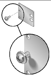
a. Using one M5 × 7 SEM screw for each rear plate, loosely install the screw in one of the three positions on the rear plate (FIGURE 4-5).
The position varies depending on the thickness of the rail in the rack. For example, FIGURE 4-5 shows where you would install the screw for the middle rack position on the rear plate.
FIGURE 4-5 Installing a Screw on the Middle Rack Position on the Rear Plate
b. Slide the rear plate in so that the screw slides into position into one of the eyelets.
The screw head should be facing the rear of the server and the other side of the rear plate should be in front of the rack post (FIGURE 4-6).
FIGURE 4-6 Installing the Rear Plate to the Side Bracket
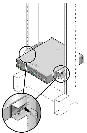
c. Tighten the screw to secure the rear plate to the eyelet on the side bracket (FIGURE 4-6).
d. Using two screws, secure the other side of the rear plate to the back of the post (FIGURE 4-7).
FIGURE 4-7 Securing the Rear Plate to the Back of the Post
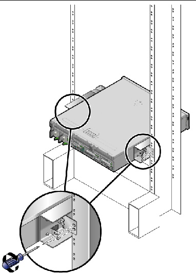
The size of the screws varies, depending on your rack.
e. Repeat Step a through Step d to secure the rear plate on the other post.
|
The hardmount kit for a 19-inch 2-post rack consists of:
| Note - The 19-inch 2-post rackmount kit supports rack web thicknesses (the width of the rack post) of 76.20 mm (3 in.), 101.6 mm (4 in.), and 127 mm (5 in.). |
FIGURE 4-8 Contents of the Hardmount 19-Inch 2-Post Kit
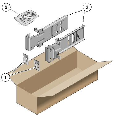
1. Get the side brackets from the rack kit (FIGURE 4-8).
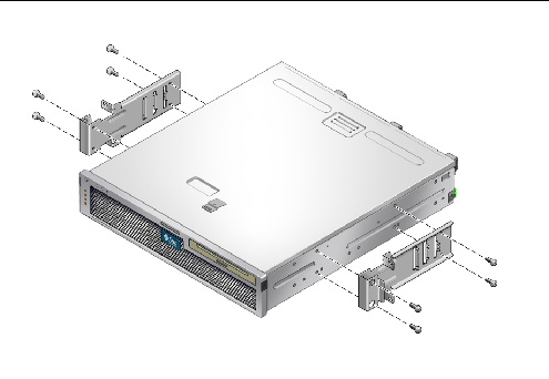
2. Using four of the M5 × 7 SEM screws for each side bracket, secure the side brackets to the sides of the server (FIGURE 4-9).
FIGURE 4-9 Securing the Side Brackets to the Side of the Server
3. Lift the server into the rack.
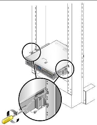
4. Using two screws for each bracket, secure the front of the server to the front of the rack (FIGURE 4-10).
The size of the screws varies, depending on your rack.
FIGURE 4-10 Installing and Securing the Server in the 2-Post Rack
5. (Optional) If your environment contains especially high vibrations, use the rear plates to further secure the server to the rack (FIGURE 4-8).
The rear plates attach to the rear of the post and to one of the three sets of eyelets on each side bracket, depending on the thickness of the post.
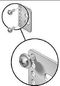
a. Using two of the M3 × 8 SEM screws for each rear plate, loosely install the screws in one of the six positions on the rear plate (FIGURE 4-11).
The position varies depending on the thickness of the rail in the rack. For example, FIGURE 4-11 shows where you would install the screws for the optimum rack position on the rear plate.
FIGURE 4-11 Installing Screws on the Optimum Rack Position on the Rear Plate
b. Slide the rear plate in so that the screws slide into position into one set of the eyelets.
The screw heads should be facing the rear of the server and the other side of the rear plate should be in front of the rack post (FIGURE 4-12).
FIGURE 4-12 Installing the Rear Plate to the Side Bracket
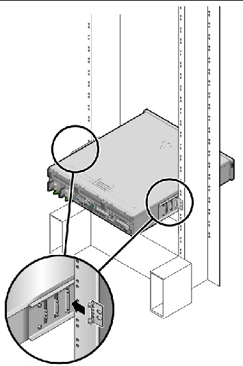
c. Tighten the screws to secure the rear plate to the set of eyelets on the side bracket (FIGURE 4-12).
d. Using two screws, secure the other side of the rear plate to the back of the post (FIGURE 4-13).
The size of the screws varies, depending on your rack.
FIGURE 4-13 Securing the Rear Plate to the Rack
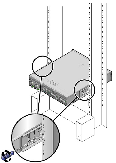
e. Repeat Step a through Step d to secure the rear plate on the other post.
|
The sliding rail mount kit for a 19-inch 2-post rack consists of:
| Note - The 19-inch 2-post sliding rail rackmount kit supports rack web thicknesses (the width of the rack post) of 76.20 mm (3 in.), 101.6 mm (4 in.), and 127 mm (5 in.). |
| Note - The front-to-back rail spacing must be at least 392 mm (15.43 in.) and not more than 863.6 mm (34 in.) from the outside face of the front rail to the outside face of the back rail. |
FIGURE 4-14 Contents of the Sliding Rail 19-Inch 2-Post Kit
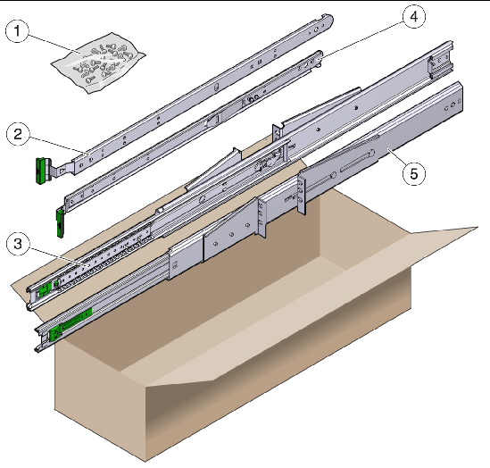
1. Obtain the slide assemblies from the rack kit (FIGURE 4-14).
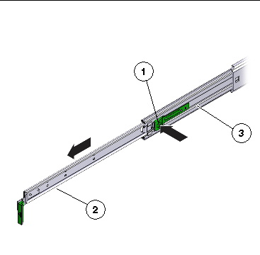
2. Press in the green button on each slide assembly and pull the right side and left side inner members (glides) completely out of the slides (FIGURE 4-15).
FIGURE 4-15 Removing Glides from the Slides
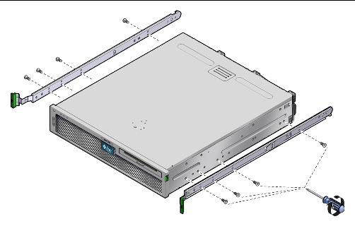
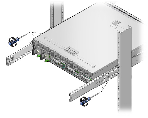
3. Using eight of the M4 x 0.5 x 5 mm Phillips panhead screws from the rackmount kit (four for each side), attach each glide to the side of the server chassis (FIGURE 4-16).
FIGURE 4-16 Attaching the Glides to the Server Chassis
4. Get the rack brackets (front and rear) from the rackmount kit (FIGURE 4-14).
5. Lift each front bracket to the desired position at the front of the rack, and attach a front bracket to each of the front rack posts (FIGURE 4-18).
To secure each bracket, use two of the M5 x 12.7 mm screws or two of the
M6 x 13 mm screws. Tighten the screws enough to secure the brackets, but leave them loose enough for adjustment later.
FIGURE 4-17 Attaching the Front Brackets to the Posts
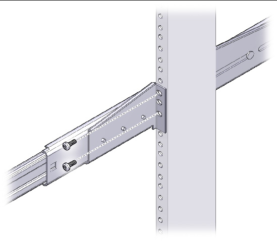
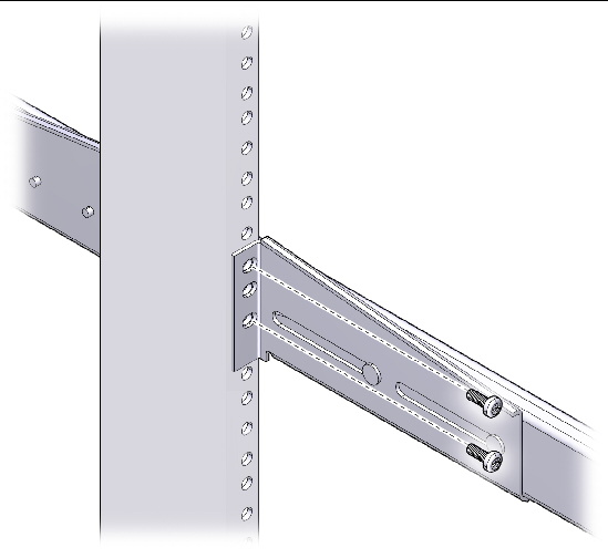
6. Lift each rear bracket to the desired position at the rear of the rack, and attach a rear bracket to each of the rear rack posts (FIGURE 4-18).
To secure each bracket, use two of the M5 x 12.7 mm screws or two of the M6 x 13 mm screws, as you did in Step 5. Tighten the screws enough to secure the brackets, but leave them loose enough for adjustment later.
FIGURE 4-18 Securing the Rear Brackets to the Rack Posts
| Note - If your rack has 10-32 holes, use the 10-32 collar screws and 10-32 threaded strips. |
7. Align the glides attached to the server with the slide assemblies in the rack.
You might find that there is too much or too little room between the two slides mounted in the rack, consequently the glides attached to the server might not align correctly with the slides in the rack. If either situation occurs, loosen the screws on the front and back brackets (Step 5 and Step 6), move the brackets inward or outward to the appropriate points, then tighten the brackets again.
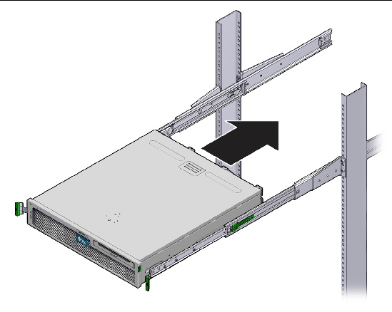
8. Push in the slide buttons and slide the server all the way into the rack enclosure (FIGURE 4-19).
FIGURE 4-19 Sliding the Server Into the Rack
9. Fully tighten the screws on the front and rear brackets.
FIGURE 4-20 Tightening the Front Bracket Screws
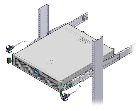
FIGURE 4-21 Tightening the Rear Bracket Screws
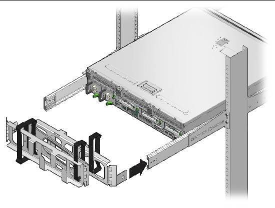
10. Attach Cable Management Arm (CMA) to rails (note labels on rails and CMA) to right (FIGURE 4-22) side.
Side with arrow attaches to inner glide; other side attached to outer member.
FIGURE 4-22 Attaching Cable Management Arm to Right Side
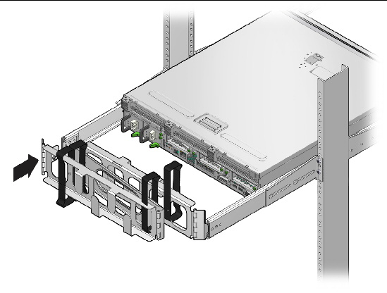
11. Attach CMA to rails (note labels on rails and CMA) to left (FIGURE 4-23) side.
Side with arrow attaches to inner glide; other side attached to outer member.
FIGURE 4-23 Attaching Cable Management Arm to Left Side

Copyright © 2011, Oracle and/or its affiliates. All rights reserved.