| Hardware Installation Guide for Sun Storage 6580 and 6780 Arrays |
| C H A P T E R 1 |
|
Product Overview |
This chapter provides an overview of the hardware and management software for the Sun Storage 6580 and 6780 Arrays. It contains the following sections:
The Sun Storage 6580 and 6780 Arrays provide a high-performance, enterprise-class, 4- and 8-Gigabit per second (Gb/s) Fibre Channel (FC) solution that combines outstanding performance with the highest reliability, availability, flexibility, and manageability.
The Sun Storage 6580 or 6780 Array can be shipped in a fully-assembled and cabled rack or as independent components. If you have purchased independent components, see Installing and Cabling Rack-Ready Trays for information about assembling your array.
The fully-assembled Sun Storage 6580 and 6780 Arrays are mounted in a Sun Rack II, which can accommodate up to 12 expansion trays. The array is scalable from a base configuration of one dual RAID controller tray and one expansion tray to a maximum configuration of one dual RAID controller tray and 12 expansion trays in one cabinet (FIGURE 1-2), up to 24 expansion trays across two cabinets (FIGURE 1-3), to a maximum of 28 expansion trays mounted in three cabinets.
FIGURE 1-1 Sun Storage 6580 and 6780 Arrays Product Overview
FIGURE 1-2 shows three sample configurations:
FIGURE 1-2 Sun Storage 6580 and 6780 Array Sample Configurations

For controller and expansion tray cabling details, see Intertray Cabling.
The configuration naming convention is the number of controller trays x the number of disk expansion trays where the first number is the controller tray and the second is the total number of trays. For example, 1x5 is one controller tray and four expansion trays, and 1x17 is one controller tray and 16 expansion trays.
FIGURE 1-3 shows one controller tray and sixteen expansion trays (1 x 17 configuration). The main cabinet arrays 1 through 12 are located in the same cabinet as the controller tray, and arrays 13 through 16 are located in an expansion cabinet.
FIGURE 1-3 Sun Storage 6780 Array 1x17 Configuration with Expansion Rack

The Sun Storage 6580 and 6780 Arrays share the same controller and expansion tray hardware. TABLE 1-1 provides a comparision of the model features.
|
IOPS[1] 115K
|
||
The Sun Storage 6580 and 6780 arrays consists of one controller tray and disk expansion trays.
The controller tray contains two redundant array of independent disks (RAID) controllers, which operate independently and provide failover capability for the data and management paths. The controller tray is configured for FC connections to expansion trays that hold disk drives, and provides RAID functionality and caching. The controller tray supports Common Storage Module 200 (also known as CSM2) expansion trays and legacy Sun StorageTek 6140 Array expansion trays.
The controller tray has two power supply-fan assemblies, and a battery backup compartment in which batteries are housed to retain cache memory in the event of a power failure. The backup batteries are accessed from a removable panel in the interconnection module.
FIGURE 1-4 Sun Storage 6580 and 6780 Array Controller Tray (Front View)

FIGURE 1-5 Controller Tray Ports (Back View)

|
Ethernet port 1 (for out-of-band array management) [2] |
|||
TABLE 1-2 shows the LEDs and indicators located at the back of the controller tray.
|
|
||
|
|
||
|
|
||
|
|
||
|
|
The speed of the drive channel is indicated: Note - Drive channel LEDs are paired. The two inner LEDs indicate the channel speed. The two outer LEDs indicate the channel is bypassed. |
|
|
|
||
|
|
The tray ID or a diagnostic code is indicated. See Controller Tray Diagnostic Codes. For example, if some of the cache memory dual in-line memory modules (DIMMs) are missing in a controller, error code L8 appears in the diagnostic display. |
|
|
|
The speed of the Ethernet ports and whether a link has been established are indicated. |
The Common Storage Module 200 (also known as CSM2) expansion tray is directly attached by a FC loop to the controller tray and cannot operate independently. The expansion trays are connected to the RAID controllers in the controller tray using the drive port connections.

Multiple expansion trays are connected using FC cables. Expansion trays are built from a 3 RU chassis and include the same controllers, power systems, and disk drives. Each expansion tray has two Fibre Channel Arbitrated Loop (FCAL) switch cards, one for each back-end loop.
In addition, each expansion tray is connected to the tray above and the tray below it by two FC cables. The FCAL switch performs trunking operations, which increases performance by opening multiple threads through the switch at one time.
Refer to Installing and Cabling Rack-Ready Trays for details on expansion tray cabling.
TABLE 1-3 describes the expansion tray disk configuration.
FIGURE 1-7 shows the location of the LEDs at the back of the expansion tray.
FIGURE 1-7 Expansion Tray LEDs and Indicators
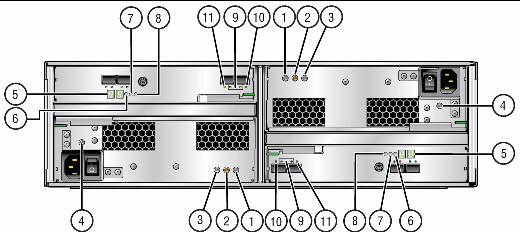
TABLE 1-4 describes the LEDs and indicators at the back of the expansion tray.
The Sun StorageTek 6140 expansion tray provides from 5 to 16 additional FC or Serial Advanced Technology Attachment (SATA) II drives. An expansion tray is cabled directly to a controller tray and cannot operate independently.
FIGURE 1-8 Expansion Tray Ports and Components (Back)

TABLE 1-5 describes the ports and components at the back of the expansion tray.
FIGURE 1-9 shows the LEDs at the back of the expansion tray.
FIGURE 1-9 6140 Expansion Tray LEDs and Indicators (Back)

For a description of numerical LED status codes, see Expansion Tray LED Status Codes.
TABLE 1-4 describes the LEDs and indicators at the back of the expansion tray.
|
|
On indicates that the correct DC power is being output from the controller power supply. |
|
|
|
Steady amber indicates that the power supply requires service. Off indicates that the power supply does not require service. |
|
|
|
Steady blue indicates that service action can be taken on the power supply without adverse consequences. Off indicates that the power supply is engaged and service action should not be implemented. |
|
|
|
On indicates that AC power is being supplied to the controller power supply. |
|
|
Seven-segment readouts indicate the ID of the tray and fault diagnostic status codes. See Expansion Tray LED Status Codes for definitions of the codes. |
||
|
|
||
|
|
Steady amber indicates that the controller requires service. Off indicates that the controller does not require service. |
|
|
|
Steady blue indicates that service action can be taken on the controller without adverse consequences. Off indicates that the controller is engaged and service action should not be implemented. |
|
|
|
The combined display indicates the expansion port link rate for the tray: |
|
|
Expansion Port Bypass1A In
|
Steady amber indicates that no valid device is detected and that the drive port is bypassed. Off indicates that there is no SFP installed or that the port is enabled. |
|
The Sun Storage 6580 and 6780 Arrays are managed by the Sun StorageTek Common Array Manager (CAM) software. CAM consists of a software suite that provides management, monitoring, and servicing capabilities. The software is delivered on CD and is available from the Sun Download Center (SDLC).
The Sun StorageTek Common Array Manager software is a web-based management software that provides both a browser interface and a command-line interface (CLI) for configuring and managing arrays on an external management host. The management software supports the Solaris 8, Solaris 9, or Solaris 10 Operating System (OS), Redhat Linux, SuSE Linux, Windows XP Pro, Windows Server 2003, and Windows Server 2008. (See the release notes for supported host operating system details.)
In addition to the full management software, you can install a compact, CLI-only version of the software. The features of the two versions compare as follows.
This install option creates a management station that contains the full set of CAM services, including:
This install option creates a compact, standalone installation which can be as little as 25MB in size. This light-weight management solution is installed on a data host attached to the array. It is installed using the CLI-only installation option and provides the following services:
For more information about the management software and installation instructions, see the Sun StorageTek Common Array Manager Installation Guide.
Data host software controls the data path between the data host and the array.
| Note - Some management hosts can also be used as data hosts. |
The data host software contains tools that manage the data path I/O connections between the data host and the array. This includes drivers and utilities that enable hosts to connect to, monitor, and transfer data in a storage area network (SAN).
The type of data host software you need depends on your operating system. You must obtain the data host software from the Sun Download Center or other source. See About Data Host Software and the Sun StorageTek Common Array Manager Software Release Notes for more information.
| Hardware Installation Guide for Sun Storage 6580 and 6780 Arrays | 820-5773-11 |
Copyright © 2009 Sun Microsystems, Inc. All rights reserved.