| C H A P T E R 4 |
|
Connecting the Management Host and Data Hosts |
This chapter describes Sun StorageTek 6140 Array cable connections for hosts. It contains the following sections:
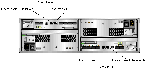
The management host directly manages Sun StorageTek 6140 Arrays over an out-of-band network. This section describes how to setup a connection between the Ethernet port of a controller (FIGURE 4-1) and the management host.
|
Note - Before you begin, ensure that the two required Ethernet cables are available. These requirements are outlined in the StorageTek 6140 Array Site Preparation Guide. |
There are three ways to establish a connection between the management host and Ethernet port 1 of an array controller:
To attach the Ethernet ports to the local area network (LAN) of the management host:
1. Locate the Ethernet port 1 for Controller A and Controller B at the back of the controller tray (FIGURE 4-1).
2. Connect an Ethernet cable to Ethernet port 1 of each controller.
3. Connect the other end of each Ethernet cable to the LAN that on which your management host resides (preferably on the same subnet).
To attach the Ethernet ports and the management port Ethernet interface to an Ethernet hub on a private subnet:
1. Locate Ethernet port 1 on Controller A and Controller B at the back of the controller tray (FIGURE 4-1).
2. Connect an Ethernet cable to Ethernet port 1 of each controller.
3. Connect the other end of each Ethernet cable to an Ethernet hub.
4. Connect an Ethernet port on the management host to the Ethernet hub.
|
Note - This method would typically be used only to establish temporary IP connectivity between the management host and the controller's Ethernet ports. |
To attach the Ethernet ports to directly to the management host using a cross-over cable:
1. Locate the Ethernet port 1 for Controller A and Controller B at the back of the controller tray (FIGURE 4-1).
2. Obtain and connect an Ethernet cross-over cable to Ethernet port 1 of each controller.
3. Connect the other end of each Ethernet cable to the LAN that on which your management host resides (preferably on the same subnet).
You can connect data hosts to access the Sun StorageTek 6140 Array through Fibre Channel (FC) switches to the array or directly to the array.
The Sun StorageTek 6140 Array has eight host connections, four per controller. To maintain redundancy, connect two data paths from each host, one to each controller.
|
Note - If using the Remote Replication premium feature, do not use Data host port 4 on both Controller A and Controller B, as it is reserved for that feature. |
You can connect the array to data hosts through external FC switches.
Before you connect data hosts, check that the following prerequisites have been met:
1. Locate the data host ports (Small Form-factor Plug-in (SFP) transceivers) at the back of the controller tray (FIGURE 4-2).
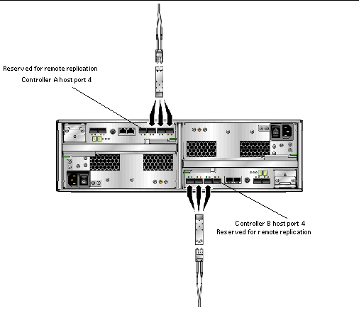
2. Connect each fiber-optic cable to the host ports of Controller A and Controller B.

|
Caution - Fiber-optic cables are fragile. Do not bend, twist, fold, pinch, or step on the fiber-optic cables. Doing so can degrade performance or cause data loss. |
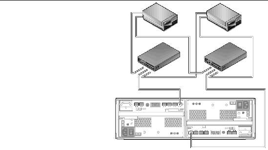
3. Connect the other end of each cable to the external switch as shown in the graphics that follow.
FIGURE 4-3 shows the data hosts connected through switches with direct connections.
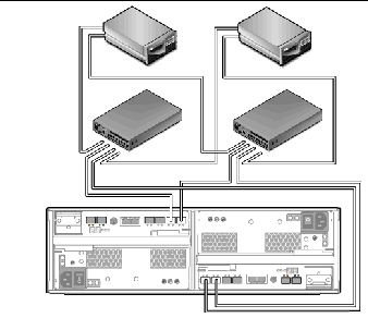
FIGURE 4-4 shows the data hosts connected through switches with cross-connections.
|
Note - The configuration in FIGURE 4-4 is not supported for use in a Sun Cluster environment. |
4. Connect the cables from the switch to the HBAs for each data host.
A direct point-to-point connection is a physical connection in which the HBAs are cabled directly to the array's host ports.
Before you connect data hosts directly to the array, check that the following prerequisites have been met:
1. Locate the host ports at the back of the controller tray (FIGURE 4-2).
2. Connect a fiber-optic cable to each host port on Controller A and Controller B that you intend to use.

|
Caution - Fiber-optic cables are fragile. Do not bend, twist, fold, pinch, or step on the fiber-optic cables. Doing so can degrade performance or cause data loss. |
3. Connect the other end of each fiber-optic cable to a data host HBA.
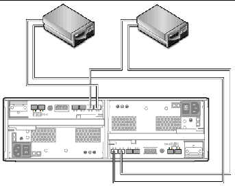
FIGURE 4-5 shows an example of a direct host connection of two data hosts with dual HBAs.
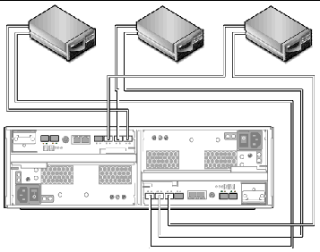
FIGURE 4-6 shows an example of a direct host connection of three data hosts with dual HBAs.
After you have connected the management host and data hosts, you are ready to install the management and data host software as described in Chapter 5.
Copyright © 2007, Sun Microsystems, Inc. All Rights Reserved.