Chapter 6 HIPAA PM Sample Scenario Tutorial
This chapter provides a basic HIPAA PM tutorial, explaining how to create and implement a sample scenario, as well as how you can use eXchange to achieve B2B solutions using the HIPAA protocol. This chapter contains the following sections:
Using This Tutorial
This chapter provides detailed procedures that describe how to construct, run, and monitor the HIPAA PM sample implementation scenario.
If you prefer to see runtime results quickly without learning the detailed procedures, use the Quick Start.
Introduction to the Sample Implementation
To perform the sample scenario implementation, you need to set up the sample projects, their environments, and their components using the eGate Enterprise Designer with eInsight and eXchange.
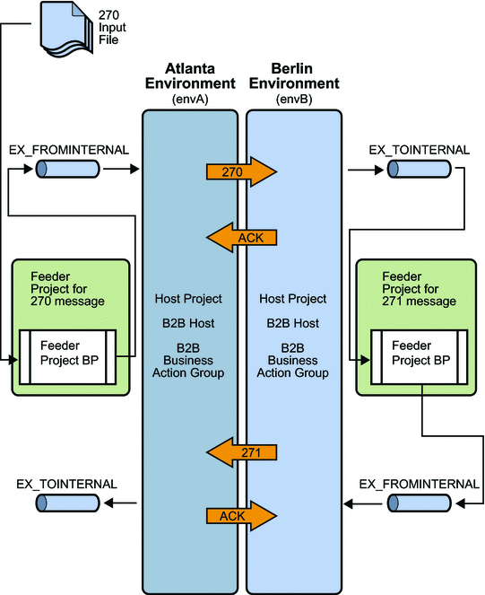
The sample implementation scenario demonstrates inbound and outbound message processing between the Atlanta Company and the Berlin Company. In the sample's business scenario, each company has an eXchange installation, and the two companies trade data. This sample scenario and its Projects demonstrate the configuration of eXchange to support HIPAA. The current viewpoint is assumed to be Atlanta.
The resulting B2B solution functions as follows:
-
HIPAA 270 Health Care Eligibility Benefit Inquiry payloads are read from a local (internal) file.
-
The individual payloads are wrapped in the inner and outer HIPAA envelopes and sent to the Berlin TP.
-
Berlin replies with a TA1 and 997 Functional Acknowledgments.
-
Berlin delivers an 271 Health Care Eligibility Benefit Response eXchange prepares and writes the individual response payloads to an internal file and displays the messages in Message Tracking.
For more information solving business problems using eXchange with eInsight and eGate, including additional details on implementation, see the eXchange Integrator User’s Guide, eInsight Business Process Manager User’s Guide, and eGate Integrator User’s Guide.
Figure 6–1 shows an operational diagram of the sample scenario.
Figure 6–1 Sample Scenario Operation
Server Configurations
The sample assumes you use default configurations for all servers, where possible, and that you make any changes in Enterprise Designer, where needed, for example:
-
Oracle – You must create a new outbound Oracle external system instance for each environment and configure it for your system, even if you imported the sample environments. Sample parameters are for reference only. Any Oracle database used by eXchange must be accessible to eGate. You must know the database's Oracle SID, user name, and password. Create and configure the eXchange database using the Oracle510.zip file. For more information see the Oracle eWay Adapter User’s Guide.
-
LDAP – You must create a new outbound LDAP external system instance for each Environment and configure it for your system, even if you imported the sample Environments. Sample parameters are for reference only. Any LDAP application used by eXchange must be accessible to eGate. For more information see the LDAP eWay Adapter User’s Guide.
-
HTTPS – For information on how to configure your HTTP server or client to use SSL, see the HTTP(S) eWay Adapter User’s Guide.
Preconfiguration for the Atlanta and Berlin Environments
This section explains the preconfiguration operations you must perform for the Atlanta and Berlin Environments.
Creating and Starting the Domains
This section explains how to create and start the Logical Host Domains for the Atlanta and Berlin Environments.
See the eGate Integrator User’s Guide for more information about eGate logical hosts, domains, and the Domain Manager feature.
 To Create and Start the Sample Domains
-
Create the domains.
-
To create the Atlanta domain, run the following script in the \logicalhost directory:
C:\ …
 logicalhost\createdomain --dname dmnA
-
To create the Berlin domain, run the following script in the \logicalhost directory:
C:\ …
 logicalhost\createdomain --dname dmnB --startingport 28000
This script creates the domain name dmnB and designates the default ports 2800x.
-
-
If the repository is not already running, start it by running the following script:
C:\ ... repository\startserver.bat
-
Start the domains.
-
Use the Domain Manager interface to make sure the new domains are started and running.
Adding a New User to ePM and Message Tracking
You must add two new ePM users, one for Atlanta and one for Berlin, using the eGate Integration Server Security Gateway.
 To Add a New User To the ePM and Message Tracking Groups
-
With the Repository running, start a new browser session.
-
Access the appropriate URL.
-
Log in to Integration Server Security Gateway using with the username Administrator and the password STC.
-
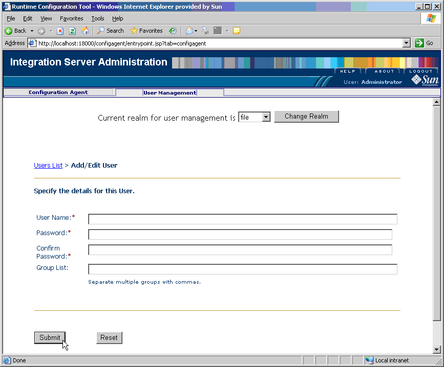
In the Integration Server Administration window, click the User Management tab.
Figure 6–2 Screen capture of Integration Server Administration, User Management tab
-
Select Add New User and supply the user name and password for the new user.
-
For Group List, type PartnerManager, MessageTracking
This step provides the following user privileges:
-
The PartnerManager role allows the specified user to log in to and use ePM.
-
The MessageTracking role allows the specified user to use the Message Tracking Web client.
-
-
When you are finished, click Submit.
-
Log out of Integration Server Administration and close the window.
Adding the Application Server Instances
You must add two new instances of the Application Server using the eGate Enterprise Manager, one for Atlanta and one for Berlin. Therefore, perform this procedure twice, once for Atlanta and once for Berlin.
 To Add Two New Application Server Instances
-
With the Repository running, install Enterprise Manager by running the following script:
C:\ …
 \emanager\install.bat
-
In the installation wizard, follow the prompts and accept the license agreement and default port (15000).
-
After the installation is complete, start Enterprise Manager server by running the following script:
C:\ …
 \emanager\startserver.bat
-
Start a new browser session and access the appropriate URL:
http://localhost:15000
-
Log in to Enterprise Manager with the user name Administrator and the password STC.
-
Select J2EE.
-
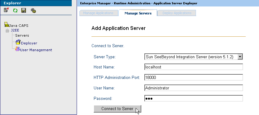
Click the Manage Servers tab, and add a new application server.
-
Server Type:Sun SeeBeyond Integration Server
-
Host Name:localhost
-
User Name:Administrator
-
Password:STC
Figure 6–3 Enterprise Manager Window
-
-
Click Connect to Server.
-
Save your changes and exit the window.
Initializing and Running Enterprise Designer
This section describes operations to perform once you have initialized and run the Enterprise Designer.
Note –
Using Enterprise Designer, increase the eDesigner_heap_size property to 1024. For more information, see the eXchange Integrator User’s Guide.
 To Initialize and Run Enterprise Designer
-
With the Repository running, start Enterprise Designer by running the following script:
C:\ …
 \edesigner\bin\runed.bat
-
Choose Update Center from the Tools menu.
-
In the Update Center wizard, follow the steps to check for updates, and to add all available updates and new modules.
-
When you are done, restart Enterprise Designer (referred to as IDE in the user interface).
Note –For more information, see the eGate Integrator User’s Guide.
-
Log in to Enterprise Designer with the user name Administrator and the password STC.
Next Steps
Patch each Logical Host domain with .jar files to ensure message validation using the EDIFECS service.
 To Patch the Domains With Files For Validation
-
To ensure correct third-party validation of messages, you must locate the following files in Enterprise Designer’s Project Explorer under Sun SeeBeyond ⇒ eXchange ⇒ Protocol Managers ⇒ HIPAA Manager ⇒ Validations ⇒ EDIFECS ⇒ Files:
-
xengine.jar
-
xe_extensions.jar
-
-
Export these files to the following locations in your installation:
-
For Atlanta:
C:\ …
 \logicalhost\is\domains\dmnA\lib\
-
For Berlin:
C:\ …
 \logicalhost\is\domains\dmnB\lib\
Note –For more information, see Third-party Validation.
-
Editing the Sample Data .xml Files
Data files are supplied with the sample scenario, which reference a path enclosed between the XML tags: <dir> … </dir>. You must first export these files using Enterprise Designer’s Project Explorer. Then, edit these files to reflect the path location where you actually export the sample scenario files.
Note –
For a list of the sample scenario’s files, see Exporting Sample Files.
 To Export the Sample Data Files
-
Locate the export files for the Atlanta sample data in Enterprise Designer’s Project Explorer under eXchange ⇒ Samples ⇒ HIPAA ⇒ RecvFromInt ⇒ Files
These files are:
-
270-SendingOutbound.dat.~in
-
270.dat.
-
-
Export these files to a folder on your C drive. It is recommended that you set up a folder structure to contain these files, under C:\temp, for example: C:\temp\eXchange\Sample\HIPAA\Data\Atlanta
-
Locate the export files that ensure Berlin returns the correct messages to Atlanta in Project Explorer, under eXchange ⇒ Samples ⇒ HIPAA ⇒ 271_FromInt_270 ⇒ Files:
These files are:
-
HIPAA_4010A1_271_template.st
-
HIPAA_dlg_270_In_Atlanta_270_In.xml
-
-
Export these files to a folder on your C drive. It is recommended that you set up a folder structure to contain these files, under C:\temp, for example: C:\temp\eXchange\Sample\HIPAA\Data\Berlin
You must make sure that the 270-SendingOutbound.dat.~in file is updated to reflect the appropriate Atlanta data path location. You may do this operation using a text editor.
 To Edit the Atlanta 270-SendingOutbound.dat.~in File
-
Make sure you have exported the sample data files.
-
Use the Enterprise Designer’s Export feature to export the sample data files to a specified location, for example:
cd /d C:\temp\eXchange\Sample\HIPAA\Data\Atlanta
-
Change directories to the subdirectory of the location where you exported the sample data files.
-
Use a text editor open the following file:
270-SendingOutbound.dat.~in
You see text that resembles the following text:
<?xml version="1.0" encoding="UTF-8"?>
<!--Sample XML file generated by XMLSPY v2004 rel. 3 U
(http://www.xmlspy.com)--><TestInput xmlns:xsi=
"http://www.w3.org/2001/XMLSchema-instance" xsi:
noNamespaceSchemaLocation="C:\HIPAASample\xsd\ServiceInput.xsd">
<dir>path</dir>
<filename>270.dat</filename>
<tradingPartner>Berlin</tradingPartner>
<service>Eligibility_AG_Profile</service>
<action>270</action>
<createnumberofmsgs>1</createnumberofmsgs>
</TestInput>
The lines preceding the last line </TestInput> have the following meaning:
-
The <dir>…</dir> line supplies the path of the directory that holds the payload data file to be processed.
-
The <filename>…</filename> line supplies the file name of the payload data file for the current transaction.
-
The <tradingpartner>…</tradingpartner> line supplies the name of the current TP.
-
The <service>…</service> line supplies the name of the Transaction Profile Group of the current TP; used in ePM.
-
The <action>…</action> line supplies the transaction number, in this case, 270.
-
The <createnumberofmsgs>…</ createnumberofmsgs> line supplies the number of messages to be created, in this case, one.
-
-
If necessary, in the line <dir>path</dir> (shown in the previous example), change the string represented by <path>, to the actual path of the directory that holds your local copy of the 270.dat file.
For example:
<dir>C:\temp\eXchange\Sample\HIPAA\Data\Atlanta</dir>
Or:
<dir>/~myname/eXchange/Sample/HIPAA/Data/Atlanta</dir>
-
If you have already run the sample and you want to experiment with other changes (such as using a payload file with a different file name, or using a TP with a different name), be sure they are also reflected here.
-
When you are finished, save your changes and exit the text editor.
You must make sure that the Berlin HIPAA_dlg_270_In_Atlanta_270_In.xml file is updated to reflect the appropriate Berlin data path location. You may do this operation using a text editor.
 To Edit the Berlin HIPAA_dlg_270_In_Atlanta_270_In.xml File
-
Make sure you have exported the sample data files.
-
Use the Enterprise Designer’s Export feature to export the sample data files to a specified location, for example:
cd /d C:\temp\eXchange\Sample\HIPAA\Data\Berlin
-
Change directories to the subdirectory of the location where you exported the sample data files.
-
Use a text editor open the following file:
HIPAA_dlg_270_In_Atlanta_270_In.xml
You see text that resembles the following text:
<?xml version="1.0" encoding="UTF-8"?> <FileAndService> <TradingPartner>Atlanta</TradingPartner> <TPProfileID></TPProfileID> <Service>Eligibility_Inb_AG</Service> <Action>271</Action> <Files Directory="path"> <Name>HIPAA_4010A1_271_template.st</Name> </Files> </FileAndService> -
If necessary, in the line <dir>path</dir> (shown in the previous example), change the string represented by path, to the actual path of the directory that holds your local copy of the HIPAA_dlg_270_In_Atlanta_270_In.xml and HIPAA_4010A1_271_template.st files.
For example:
<dir>C:\temp\eXchange\Sample\HIPAA\Data\Berlin</dir>
Or:
<dir>/~myname/eXchange/Sample/HIPAA/Data/Berlin</dir>
-
If you have already run the sample and you want to experiment with other changes (such as using a payload file with a different file name, or using a TP with a different name), be sure they are also reflected here.
-
When you are finished, save your changes and exit the text editor.
Note –For more information, see the eXchange Integrator User’s Guide.
Constructing the Environments
In implementing HIPAA PM Projects, you must set up at least one Environment for each eXchange installation. The sample scenario is set up to operate on one machine but mimic two TPs.
As a result, for the sample scenario, you need to construct the Environments as explained under the following sections:
Using Environment Explorer
You perform these operations using Enterprise Designer’s Environment Explorer and its canvas windows.
The sample Environments contain the following types of components:
-
Instances for external systems accessed by eWays
-
Instance for the B2B Service Configurator external system
-
Instance for the Logical Host
For example, the Oracle external system must be configured to reference your Oracle setup. Other external systems (for example, the File and Batch eWays) have configurations that may differ depending on your system setup, and so forth. Also, you may be using nonstandard ports or user name/password combinations.
The remainder of this section describes the procedures to construct the sample scenario’s Environments.
Note –
Before you begin, make sure you have followed the preliminary instructions provided under Getting Started.
Setting up the Environments
This section explains how to create the sample’s Environments for Atlanta and Berlin. Use the procedures to set up Atlanta first, then Berlin.
 To Create the Basic Components
-
On Enterprise Designer, near the lower left of the window, click the Environment Explorer tab.
-
On the Environment Explorer tree, right-click the Repository and, on the context menu, click New Environment.
-
Name the newly created Environment envA (envB for Berlin).
-
Right-click envA (envB for Berlin) and, on the menu, click New Logical Host and name the Logical Host lhA (lhB for Berlin).
-
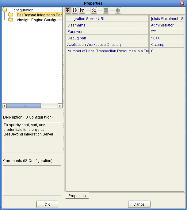
Right-click IntegrationSvr1 and select Properties from the context menu.
The Properties dialog box for IntegrationSvr1 appears. See the figure below.
Figure 6–4 Integration Server Properties Dialog Box: Environment
-
For lhA ⇒ IntegrationSvr1 on Environment Explorer, set the Configuration ⇒ SeeBeyond Integration Server properties as follows:
-
For the rest of the IntegrationSvr1 properties settings, accept the defaults.
-
Create a Sun SeeBeyond JMS IQ Manager under IntegrationSvr1 and name it SBJMSIQMgr1.
-
Right-click SBJMSIQMgr1 and select Properties from the context menu.
The Properties dialog box for SBJMSIQMgr1 appears.
-
For lhA ⇒ SBJMSIQMgr1 on Environment Explorer, set the Configuration ⇒ SeeBeyond JMS IQ Manager Configuration property as follows:
Password: STC
 To Create and Configure the Oracle External System
-
On Enterprise Designer, on the Environment Explorer tree, right-click envA (envB for Berlin) and, on the context menu, click New Oracle External System.
-
Name the new component esOracleand click OK.
These actions create, for the current Environment, an external system instance for the Oracle eWay in outbound mode.
Note –The eXchange database uses Oracle. For more information on Oracle requirements for eXchange and HIPAA PM, see the Readmefile that accompanies HIPAA PM.
-
Right-click esOracle and select Properties from the context menu.
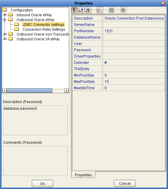
The Properties dialog box for the external system appears. See the figure below.
Figure 6–5 Oracle External System Properties Dialog Box: Environment
-
Configure the Configuration ⇒ Outbound Oracle eWay ⇒ JDBC Connector settings properties for esOracle as follows:
-
Description: Oracle Connection Pool Datasource
-
ServerName: Host name of the Oracle server machine
-
PortNumber: 1521 (change this value only if your Oracle system administrator changed the default)
-
DatabaseName: SID for your current Oracle system
-
User: Valid user ID for the current Oracle system
-
Password: Valid password for the current Oracle system (masked)
-
Driver Properties: Blank, for this sample
-
Delimiter: #
-
TNS Entry: Blank, for this sample
-
MinPoolSize: 0
-
MaxPoolSize: 10
-
MaxIdleTime: 0
-
-
Configure the Configuration ⇒ Outbound Oracle non-Transactional eWay ⇒ JDBC Connector settings properties for esOracle as follows:
-
Description: Oracle non-Transactional Connection Pool Datasource
-
ServerName: Host name of the Oracle server machine
-
PortNumber: 1521 (change this value only if your Oracle system administrator changed the default)
-
DatabaseName: SID for your current Oracle system
-
User: Valid user ID for the current Oracle system
-
Password: Valid password for the current Oracle system (masked)
-
Driver Properties: Blank, for this sample
-
Delimiter: #
-
TNS Entry: Blank, for this sample
-
MinPoolSize: 0
-
MaxPoolSize: 10
-
MaxIdleTime: 0
-
-
When all properties have been configured correctly for your site, click OK.
 To Create and Configure the LDAP External System
-
Create a new LDAP external system (New ⇒LDAP External System) under envA (envB for Berlin) and name it esLDAP.
-
Set the Environment Configuration ⇒ Connection properties for esLDAP as follows:
-
Initial Context Factory: com.sun.jndi.ldap.LdapCtxFactory
-
Provider URL: As necessary for your system, according to the provided syntax. You need to provide one organizational unit for Atlanta(exA) and another one for Berlin (exB), For example, ldap://mycompany.co.in:1389/ou=exA,dc=co,dc=in
-
Authentication: simple
-
Principal: As necessary for your system. For example, Manager
-
Credentials: Password, as necessary for your system. For example, exchange
Note –A separate LDAP external system instance is required for each B2B Host.
-
-
For all other esLDAPproperties, accept the defaults.
 To Create and Configure the B2B Configurator Service External System
-
Create a B2B Service Configurator (New ⇒ B2B Configurator Service) external system under envA and name it esB2BService.
-
Set the environment-configuration ⇒ Database Settings properties for esB2BService as follows:
-
Type: Oracle
-
URL: Points to the eXchange database; an example of the URL syntax is: jdbc:oracle:thin:@hostname:port:exchange
-
UserName: Valid user ID for the current Oracle system. For example, ex_admin
-
Password: Valid password for the current Oracle system (masked). For example, ex_admin
-
-
Set the environment-configuration ⇒ JMS Settings properties for esB2BService as follows:
-
Set the environment-configuration ⇒ JMS Settings properties for esB2BService as follows:
-
JMS Server URL: Points to the IQ Manager port. The envA Logical Host is on 18000 (envB on 28000), the IQ Manager port for envA is 18007 (28007 for envB). This port number is listed in the Domain Manager for the current Logical Host; an example of the URL syntax is: stcms://hostname:port
-
Security Principal: Administrator
-
Security Credentials: STC (masked)
-
Connection Factory: connectionfactories/topicconnectionfactory
-
Resend Topic: topics/EX_TODELIVERY
-
Timeout Topic: topics/EX_ERROR
-
Business Protocol Topic for Batching: topics/EX_BATCHER
-
Delivery Protocol Topic for Batching: topics/EX_DELIVERYBATCHER
-
-
For the rest of the esB2BService properties settings, accept the defaults.
 To Create and Configure the File External Systems
-
Create a new File eWay (New ⇒ File External System) in inbound mode under envA and name it esFileA.
-
Set the Configuration ⇒ Inbound File eWay ⇒ Parameter Settings property for esFileA as follows:
Directory:
C:/temp/eXchange/Sample/HIPAA/Data/Atlanta
Note –Make sure this folder and the folder for envB are correctly configured under the appropriate parameter in ePM. It is recommended that you create an additional folder under HIPAA named Errors.
-
Set the Configuration ⇒ Outbound File eWay ⇒ Parameter Settings property (for DLQ and processing errors) for esFileA as follows:
Directory:
C:/temp/eXchange/Sample/HIPAA/Errors/Atlanta
-
For all other File eWay (esFileA and esFileB) properties, accept the defaults.
-
Create a new File eWay (New ⇒ File External System) in inbound mode under envB and name it esFileB.
-
Set the Configuration ⇒ Inbound File eWay ⇒ Parameter Settings property for esFileB as follows:
Directory:
C:/temp/eXchange/Sample/HIPAA/Data/Berlin
-
Set the Configuration ⇒ Outbound File eWay ⇒ Parameter Settings property (for DLQ and processing errors) for esFileB as follows:
Directory:
C:/temp/eXchange/Sample/HIPAA/Errors/Berlin
 To Create and Configure the Additional External Systems
-
In Enterprise Designer, on the Environment Explorer tree, right-click envA (envB for Berlin) and, on the context menu, click New Batch Local File System.
-
Name the new external system esBLF, and click OK.
These operations create, for the Environment, an external system for the Batch eWay in local file mode.
-
In the new external systems’ Properties dialog boxes and accept the defaults.
Note –When you are finished with each Properties dialog box, click OK.
-
Create an HTTP eWay (client mode) external system under envA (envB for Berlin) and name it esHTTP.
-
Open the Properties dialog boxes for esHTTP and accept the defaults.
Note –You must create HTTP(S) external systems if you want to use the sample scenario with HTTP(S).
-
Create an HTTP eWay (server mode) external system under envA (envB for Berlin) and name it esHTTPserver.
-
Open the Properties dialog boxes for esHTTPserver and accept the defaults.
Note –When you build a B2B Host Deployment Profile, eXchange automatically creates another external system on the chosen Environment. This external system is called an eXchange service. For more information on this service, see the eXchange Integrator User’s Guide. Also, see Constructing the B2B Host Project.
When You Are Finished for Atlanta
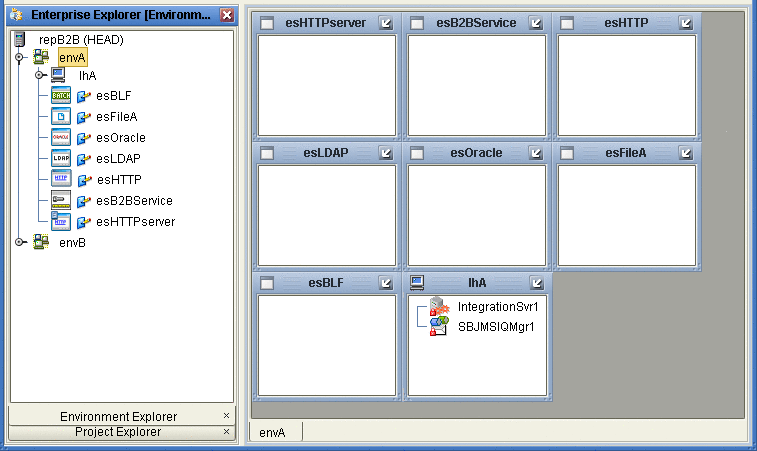
Result: You have set up the Environment for Atlanta, envA. See Figure 6–6.
Figure 6–6 Sample Scenario Atlanta Environment
Collapse the envA Environment Explorer tree, click Save All, and close all canvases.
When You Are Finished for Berlin
Result: You have set up the Environment for Berlin, envB, which appears directly under envA on the Environment Explorer tree. See Figure 6–6.
Collapse the envB Environment Explorer tree, click Save All, and close all canvases.
Final Result: You have now finished setting up the Environments for Atlanta and Berlin, including the external system components to be used by both.
Constructing the Projects
This section explains how to construct the Projects in the HIPAA PM in order to run the sample scenario.
This operation includes:
-
Using installed Projects (in Project Explorer) for the sample scenario
-
Setting up and configuring Project components
-
Associating each Project with the appropriate Environment(s)
-
Mapping and building the Project’s Deployment Profile
-
Deploying the Deployment Profile, if necessary
Building a Deployment Profile creates the application .ear file for the Project. After creating this file, you must deploy it for all Deployment Profiles except the B2B Host.
You perform these operations using Enterprise Designer’s Project Explorer and its canvas windows.
The remainder of this section describes the necessary procedures under the following sections:
Constructing the B2B Host Project
This section explains how to set up, and configure the HIPAA PM sample scenario’s B2B Host Project, HipaaHost. Constructing the B2B Host Project creates an eXchange service that acts as a channel manager and provides a connection to the eXchange database. You must build two Deployment Profiles, one for each company, Atlanta and Berlin. However, you do not deploy these Deployment Profiles.
 To Build the B2B Host’s Deployment Profile for Atlanta
-
On Enterprise Designer’s Project Explorer tree, right-click HipaaHost under eXchange ⇒ B2BHosts and, on the context menu, choose New and click Deployment Profile.
-
In the resulting dialog box, name the new Deployment Profile dpHost_A, point it at envA, make sure it is using only the cmHIPAA Connectivity Map, and click OK.
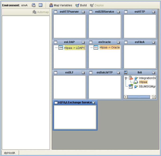
Deployment Editor opens. Its left pane shows the HIPAA B2B Host instance, the Oracle1 external application, and the LDAP1 external application. These are the components created in the Connectivity Map cmHIPAA.
The Deployment Editor right pane contains windows representing the Logical Host and external systems created in envA.
-
Click Automap to map the components.
The components in the left pane automatically map to the appropriate windows on the right pane of Deployment Editor for dpHost_A. .
Figure 6–7 Deployment of dpHost A
-
Click Save.
-
Click Build to build the Deployment Profile.
A dialog box appears, indicating the status of the build operation. A new service, the HIPAA eXchange Service, is created and assigned to the current Deployment Profile and Environment.
You may view this HIPAA eXchange Service on envA, in the Environment Explorer tree, as well as in the right pane of Deployment Editor for dpHost_A.
Note –Do not deploy the B2B Host Project.
If the build operation is not successful, repeat the steps in this procedure, carefully rechecking every action. When the build is successful, go to the next step.
Note –Building Deployment Profiles for large Projects may take approximately 10 to 15 minutes or more.
-
When you are finished, click Save All and close all canvases.
 To Build the B2B Host’s Deployment Profile for Berlin
-
On Enterprise Designer’s Project Explorer tree, right-click HipaaHost under eXchange ⇒ B2BHosts and, on the context menu, point at New and click Deployment Profile.
-
In the resulting dialog box, name the new Deployment Profile dpHost_B, point it at envB, make sure it is using cmHIPAA, and click OK.
-
In Deployment Editor, click Automap to map the components.
-
Click Save.
-
Build the Deployment Profile for Berlin in the same way as you did for Atlanta, except make sure to use envB and cmHostB.
The HIPAA eXchange Service is created and assigned to the current Deployment Profile and Environment. Do not deploy the B2B Host Project. Once more, if there are any errors, troubleshoot until you are ready to go to the next step.
-
When you are finished, click Save All and close all canvases.
Result: You have now finished constructing the B2B Host Project, including creating, mapping, and building Deployment Profiles for Atlanta and Berlin.
eXchange Deployment Project
This section explains how to set up, build, and deploy Atlanta and Berlin Deployment Profiles in the eXchange Deployment Project. This Project makes all of the core B2B services and processing available to the application .ear files built from the Deployment Profiles.
To complete this operation, you must set up a Connectivity Map for HIPAA OTD validation and Deployment Profiles for both Atlanta and Berlin. You must map, build, and deploy both Deployment Profiles.
Creating the Validation Connectivity Map
To complete this operation, you must deploy OTD validation BPs using a Connectivity Map, to allow you to configure the Trading Partner Profiles to specify the custom validation handlers. You must then map, build, and deploy two Deployment Profiles, one each for Atlanta and Berlin.
 To Create the OTD Validations Connectivity Map
-
Create a Connectivity Map using Project Explorer, under eXchange ⇒ Deployment, named, for example, cmHIPAAValidation (or a convenient name for your system, with fewer characters).
-
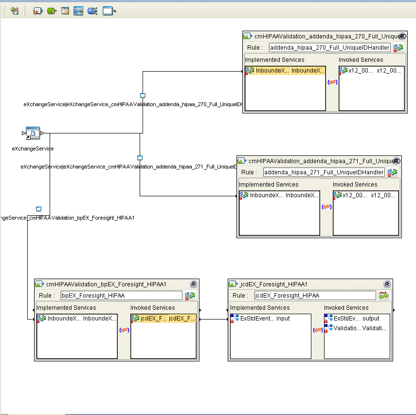
From Project Explorer, drag Sun SeeBeyond ⇒ eXchange ⇒ User Components ⇒ OTD Validations ⇒ HIPAA ⇒ 2000_Addenda ⇒ addenda_hipaa_270_Full_UniqueIDHandler onto the Connectivity Map canvas.
-
From the same Project Explorer location, drag the addenda_hipaa_271_Full_UniqueIDHandler component onto the Connectivity Map canvas.
-
Drag one eXchangeService from the eXchange ⇒ Deployment folder onto the canvas.
-
Connect eXchangeService to each of the other components.
-
Locate the files in the Project Explorer based on the validation service you want to use and drag it onto the Connectivity Map.
-
Drag the respective JCD file onto the Connectivity Map.
-
EDIFECS ⇒ JCDs⇒jcdEX_HIPAA_ValidationService
-
FORESIGHT ⇒ JCDs⇒jcdEX_Foresight_HIPAA as shown in Figure 6–8
-
-
Rename the respective JCD component in the Connectivity Map by removing the cmHIPAAValidation prefix.
-
Connect all of the components as shown in Figure 6–8.
Figure 6–8 OTD Validation Connectivity Map Linking
-
Open and save all the default properties for the eWays on the Connectivity Map.
-
Update the instreamapi.jar file with the correct version of the jar file from the Foresight engine.
-
Click Save All then close the Connectivity Map.
Building and Deploying the Deployment Profiles
When you are finished, you must create Deployment Profiles for both Atlanta and Berlin. These Deployment Profiles are for the eXchange Deployment Project.
 To Build and Deploy the eXchange Deployment Project’s Deployment Profile for Atlanta
-
On Enterprise Designer’s Project Explorer tree, right-click Deployment and, on the context menu, point at New and click Deployment Profile.
-
In the resulting dialog box, name the new Deployment Profile dpA, point it at envA, make sure it is using all the checked Connectivity Maps, and click OK.
-
On Deployment Editor, click Automap to map the components.
-
Click Build to build the Deployment Profile for Atlanta.
-
Click Deploy to deploy the Deployment Profile.
Note –After each of the operations, map, build, and deploy, you receive a status message. If you receive any errors, troubleshoot your previous procedures, as necessary. Deploying Deployment Profiles may take as long or longer than building them.
-
When you are finished, click Save All and close all canvases.
 To Build and Deploy the eXchange Deployment Project’s Deployment Profiles for Berlin
-
On Enterprise Designer’s Project Explorer tree, right-click Deployment and, on the context menu, point at New and click Deployment Profile.
-
In the resulting dialog box, name the new Deployment Profile dpB, point it at envB, make sure it is using all the checked Connectivity Maps, and click OK.
-
On Deployment Editor, click Automap to map the components.
-
Click Build to build the Deployment Profile for Berlin.
-
Click Deploy to deploy the Deployment Profile.
-
When you are finished, click Save All and close all canvases.
Result: You have now finished constructing the eXchange Deployment Project, including creating, mapping, building, and deploying Deployment Profiles for Atlanta and Berlin.
Constructing the 271_FromInt_270 Project
This section describes how to set up, build, and deploy the Berlin Deployment Profile for the 271_FromInt_270 Project. This Project operates with envB and makes sure the HIPAA 271 message is returned from Berlin to Atlanta.
Updating the bp271 Business Process
You must make sure the Berlin system is using the data file path listed under Editing the Sample Data .xml Files by checking the bp271 BP in 271_FromInt_270. To do this action, open eXchange ⇒ Samples ⇒ HIPAA ⇒ 271_FromInt_270 ⇒ BPs ⇒ bp271 in Project Explorer.
The BP structure appears in Business Process Editor, in Enterprise Designer’s right pane. See Figure 6–9.
Figure 6–9 Business Process Editor: bp271
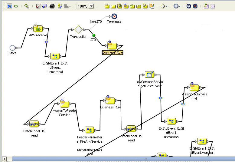
Make sure that the path given in the indicated component, in the previous figure, reflects your Berlin data path, for example:
C:\temp\eXchange\Sample\HIPAA\Data\Berlin |
This is also the path location of the HIPAA_dlg_270_In_Atlanta_270_In.xml and HIPAA_4010A1_271_template.st files.
Note –
This setup has been created for the purpose of the sample scenario only. It is recommended that, when creating your own inbound BPs, you configure the BP to read this type of path information from the inbound eWay.
Building and Deploying the Deployment Profile
This section describes how to build and deploy the 271_FromInt_270 Project’s Deployment Profile for Berlin.
 To Build and Deploy the 271_FromInt_270 Project’s Deployment Profile for Berlin
-
On Enterprise Designer’s Project Explorer tree, right-click Deployment and, on the context menu, point at New and click Deployment Profile.
-
In the resulting dialog box, name the new Deployment Profile dp271_B, point it at envB, make sure it is using all the checked Connectivity Maps, and click OK.
-
On Deployment Editor, click Automap to map the components.
-
Click Build to build the Deployment Profile for Berlin.
-
Click Deploy to deploy the Deployment Profile.
-
When you are finished, click Save All and close all canvases.
Result: You have now finished setting up the 271_FromInt_270 Project, including creating, mapping, building, and deploying Deployment Profile for Berlin only (there is no Atlanta Deployment Profile for this Project).
Constructing the Remaining Projects’ Deployment Profiles
Construct the following Projects’s Deployment Profiles, as shown under eXchange in Project Explorer, in the same way you have done for the previous Projects in the sample scenario:
-
ePM
-
Tracker
-
Sub_DLQ
-
Sub_ProcErrors
-
RecvFromInt
-
RecvFromTP; use only the BatchLocalFile sub-Project.
-
SendToInt
To construct the remaining Projects’ Deployment Profiles
Locate, name, and deploy Deployment Profiles for the Projects shown in the previous list, as depicted in Table 6–1.
Final Result: You have constructed, built, and deployed (if necessary) all the Projects’ Deployment Profiles for the sample scenario.
Summary of Sample Scenario Projects
Table 6–1 provides a summary list of the sample scenario’s Projects, their Deployment Profiles, and corresponding Environments. It is recommended that you construct the Projects and their Deployment Profiles in the order shown in the table.
Table 6–1 Sample Scenario Projects Summary|
Location Under eXchange |
Projects |
Deployment Profiles |
Environments |
|---|---|---|---|
|
B2BHosts |
HipaaHost |
dpHost_A; not deployed |
envA |
|
dpHost_B; not deployed |
envB |
||
|
Deployment |
eXchange Deployment |
dpA |
envA |
|
dpB |
envB |
||
|
Samples ⇒ HIPAA |
271_FromInt_270 |
dp271_B |
envB |
|
GUI |
ePM |
dpePM_A |
envA |
|
dpePM_B |
envB |
||
|
Tracker |
dpTrack_A |
envA |
|
|
dpTrack_B |
envB |
||
|
Error |
Sub_DLQ |
dpSDLQ_A |
envA |
|
dpSDLQ_B |
envB |
||
|
Sub_ProcErrors |
dpSPErrors_A |
envA |
|
|
dpSPErrors_B |
envB |
||
|
Samples ⇒ HIPAA |
RecvFromInt |
dpRecvInt_A |
envA |
|
RecvFromTP |
dpRecvTP_A |
envA |
|
|
dpRecvTP_B |
envB |
||
|
SendToInt |
dpSendInt_B |
envB |
Importing and Configuring Components in ePM
This section explains how import, create, and configure TPs, Action Groups, Transaction Profiles, and Schedules in the HIPAA PM sample scenario, using the eXchange ePM. Additionally, the section describes how to use ePM to set the configuration parameter values for the Transaction Profiles and their related components.
Note –
For detailed procedures on how to use TPs, Action Groups, Transaction Profiles, and Schedules, see the eXchange Integrator User’s Guide.
Getting Started
Before you begin, it is recommended that you do all the procedures given in the previous sections of this chapter. Also, your Integration Server must be running. Also, your LDAP system and eXchange database (Oracle) must be running and accessible. However, Enterprise Designer does not need to be running.
Note –
For a general description of the outbound and inbound messaging ToPartner and FromPartner model used by ePM, see Configuring ePM: ToPartner and FromPartner Messaging Model.
You must do the procedures given under Running ePM to run ePM. In addition, after you run ePM, it is recommended that you do the procedures given under Importing B2B Hosts and Importing TPs.
Note –
If you want, you can create your own B2B Hosts and TPs using the procedures given in this section and using the sample scenario B2B Hosts and TPs as models. For more details, see the eXchange Integrator User’s Guide.
The remainder of this section explains these operations.
Note –
For detailed information on configuring ePM, see Chapter 4, Configuring HIPAA PM.
Exporting the necessary ePM Files
The ePM export files for the B2B Hosts, TPs, and Schedules are located in Project Explorer under eXchange, as follows:
-
ePMImport ⇒ HIPAA ⇒ Hosts ⇒ envA_HIPAA_Host.exp and envB_HIPAA_Host.exp
-
ePMImport ⇒ HIPAA ⇒ Schedulers ⇒ envA_HIPAA_S1.exp and envB_HIPAA_S1.exp
-
ePMImport ⇒ HIPAA ⇒ TP_Profiles ⇒ envA_HIPAA_TP_Berlin.exp and envB_HIPAA_TP_Atlanta.exp
For more information, see Exporting ePM Files. It is recommended that you set up a folder structure to contain these files, which reflects this organization, for example:
C:\temp\eXchange\Sample\HIPAA\TP_Profiles |
Note –
For more information on how to use ePM, see the eXchange Integrator User’s Guide.
Running ePM
This section explains how to start running eXchange ePM.
 To Run ePM
-
Start a browser session.
-
Enter the Logical Host name and ePM port number with epm appended, as follows:
http://logicalhost:port+1/epm
For example:
http://localhost:18001/epm
-
When the sign-in window appears, enter your Enterprise Manager user name (or the new user described under Adding a New User to ePM and Message Tracking), as well as the appropriate password, and click Sign In.
The initial ePM window appears. See Figure 6–10.
Figure 6–10 ePM Window
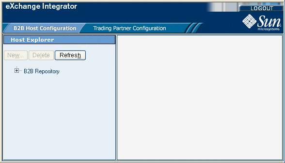
The ePM window has the following sections:
Importing B2B Hosts
Your next step is importing the Atlanta and Berlin B2B Host files, as explained under this section.
This sample scenario has the following B2B Hosts:
-
envA_HIPAA_Host: For Atlanta.
-
envB_HIPAA_Host: For Berlin.
 To Import the envA B2B Host
-
Log in to ePM for envA (dmnA).
-
Click the B2B Host Configuration tab, if Host Explorer is not already displayed.
-
In Host Explorer, click and expand B2B Repository.
-
Select the B2B Host envA_HIPAA_Host.
-
At the bottom of ePM Canvas, click Import.
-
When you are finished, click Save.
 To Import the envB B2B Host
-
Log in to ePM for envB (dmnB).
-
Click the B2B Host Configuration tab, if Host Explorer is not already displayed.
-
In Host Explorer, click and expand B2B Repository.
-
Select the B2B Host envB_HIPAA_Host.
-
At the bottom of ePM Canvas, click Import.
-
When you are finished, click Save.
Using Schedules
Next, you must import the Schedules for the B2B Hosts.
 To Import a Schedule
-
Log in to ePM for envA (dmnA) for Atlanta; use envB (dmnB) for Berlin.
-
Click the B2B Host Configuration tab.
-
ePM Explorer with this tab selected appears.
-
Click the Schedule icon in ePM Explorer.
-
Select the Schedule file you want to import (envA_HIPAA_S1.exp for envA and envB_HIPAA_S1.exp for envB).
-
Click Import.
-
When you are finished, click Save.
 To Modify an Existing Schedule
-
Log in to ePM for envA (dmnA) for Atlanta; use envB (dmnB) for Berlin.
-
Click the B2B Host Configuration tab.
ePM Canvas with this tab selected appears.
-
Click the Settings tab.
-
In ePM Canvas, modify the scheduling information for the current Schedule, as necessary. This information is for inbound only.
-
When you are finished, click Save.
Importing TPs
Your next step is importing or creating the Atlanta and Berlin TP files, as explained under this section. Keeping track of the TPs, where they are sent from, and where they are received depends on which company you consider to be your current company. See Configuring ePM: ToPartner and FromPartner Messaging Model.
This sample scenario has the following TPs:
-
Berlin: For Atlanta.
-
Atlanta: For Berlin.
Note –Also, you may create and construct these TPs yourself, using the sample TPs as models.
This sample scenario has the following TP files (under TP_Profiles):
-
envA_HIPAA_TP_Berlin.exp: For Atlanta.
-
envA_HIPAA_TP_Atlanta.exp: For Berlin.
 To Import the Berlin TP to EnvA
-
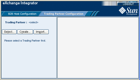
Click the Trading Partner Configuration tab.
The ePM window with this tab selected appears. See Figure 6–11.
Figure 6–11 ePM Window With Trading Partner Configuration Tab Selected
-
From this window, click Import.
The Import a Trading Partner - Step 1 of 2 window appears in ePM Canvas.
-
Name the TP Berlin.
-
Browse to the folder where you have stored your TP files and select envA_HIPAA_TP_Berlin.exp, then click Next.
The Import a Trading Partner - Step 2 of 2 window appears.
-
Choose envA_HIPAA, from the pull-down menu.
-
Click Finish.
 To Locate the Berlin TP in the ePM Window
-
In the upper left side of the ePM window, click Select.
The Select the Trading Partner to Configure window appears in ePM Canvas.
-
Click Search on the canvas.
Any available TPs appear directly below.
-
In this case, you are looking for Berlin, which appears.
-
Click the TP name, in this case Berlin, to configure the TP.
 To Import the Atlanta TP to envB
-
Click the Trading Partner Configuration tab.
The ePM window with this tab selected appears.
-
From this window, click Import.
The Import a Trading Partner - Step 1 of 2 window appears in ePM Canvas.
-
Name the TP Atlanta.
-
Browse to the folder where you have stored your TP files and select envB_HIPAA_TP_Atlanta.exp, then click Next.
The Import a Trading Partner - Step 2 of 2 window appears.
-
Choose envB_HIPAA, from the pull-down menu.
-
Click Finish.
 To Locate the Atlanta TP in the ePM Window
Using Action Groups and Transaction Profiles
You do the actual configuration of Action Groups and Transaction Profiles using parameters available using the following levels of the ePM Explorer tree:
-
Business Protocols
-
Delivery Protocols
-
Transports
More information on how to configure Transport parameters is available in the eXchange Integrator User’s Guide. For information on how to configure these parameters in the sample scenario, see Configuring Transports.
Configuring the Sample Scenario
You may use the ePM for the Projects in the sample scenario as a model to complete the configuration of ePM. Enter information in ePM as shown in the sample. For more information, see Chapter 4, Configuring HIPAA PM and the eXchange Integrator User’s Guide.
Using Parameters in ePM
Many of the Business and Delivery Protocol parameters are the same, regardless of the PM and business communication protocol you are using. However, some of them are HIPAA PM-specific and are only present for HIPAA.
This section describes these parameters under:
For more information on these parameters, see Configuring HIPAA PM ePM Parameters.
Note –
For more information on parameters not described under this section, see the eXchange Integrator User’s Guide.
 To Enter an Override Value for a Parameter
-
Click the check box next to the parameter you want to override, under the Override column (see Figure 6–12 for an example).
-
Enter the appropriate override in the text box for the parameter.
-
Click Save.
ePM Configuration General Operation
In the sample scenario, you import preconfigured B2B Hosts and TPs.
When you are configuring your own (for example, if you are creating B2B Hosts and TPs from scratch), it is recommended that you use the following general order of configuration operations when setting values in ePM:
-
On the B2B Host Configuration tab, create a new B2B Host Transaction Profile.
-
Create a new Action Group (ePM here calls this a Business Action Group) for the B2B Host. Be sure to choose the correct Delivery Action and External Transport for the Action Group’s Business Actions.
-
On the Trading Partner Configuration tab, create a new TP.
-
For the new TP, select the Transaction Profile from the B2B Host.
-
Choose the necessary settings (Settings tab) for the current TP Transaction Profile.
-
Open any applicable Business Actions and set appropriate overrides, as necessary.
Interchange Envelope Parameters
The HIPAA PM-specific Interchange Envelope (outer envelope or ISA) parameters appear in ePM Canvas as shown in Figure 6–12. The example shown is for the Berlin TP’s 270 ToPartner Transaction Profile.
Figure 6–12 HIPAA PM-specific Interchange Envelope Parameters: Example
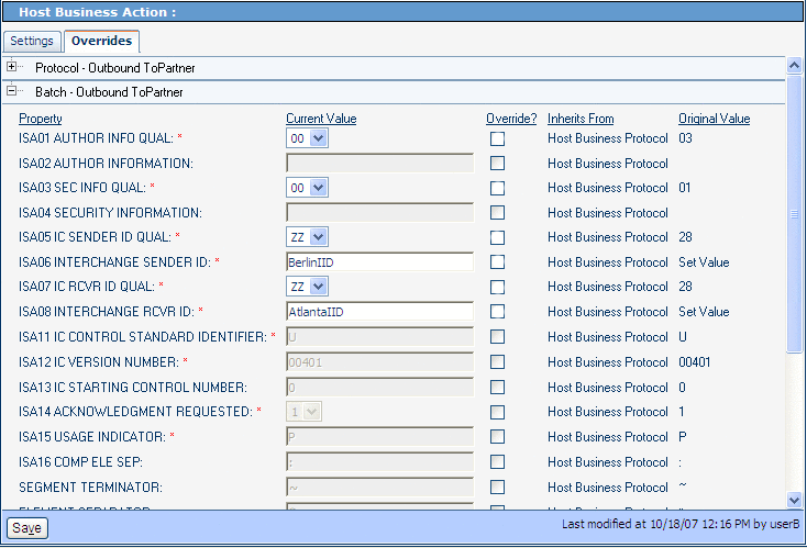
You may display the example in Figure 6–12 by using ePM Explorer, under B2B Repository ⇒ envA_HIPAA ⇒ Business Protocols ⇒ HIPAA.
As you can see, there are no override values entered in Figure 6–12, and the configuration accepts all the defaults. You may override the defaults for any parameter by clicking a check box under Override and entering a different value, as necessary.
You may, of course, do the same override operation with other ePM parameters, as described under Configuring eXchange Partner Manager: Overview.
Functional Group Parameters
The HIPAA PM-specific Functional Group (inner envelope or GS) parameters appear in ePM Canvas as shown in Figure 6–13. The example shown is for the Atlanta TP’s 270 FromPartner Transaction Profile.
Figure 6–13 HIPAA PM-specific Functional Group Parameters: Example
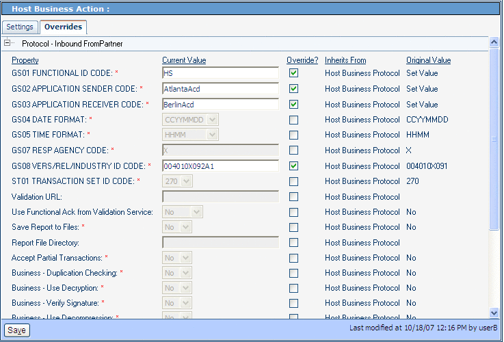
You may display the example in Figure 6–12 by using ePM Explorer, under B2B Repository ⇒ envA_HIPAA ⇒ Business Protocols ⇒ HIPAA.
As you can see, four overrides value has been entered in Figure 6–13, and the configuration uses the defaults for all other displayed parameters. As explained previously, you may override the default values, as necessary.
Necessary Overrides
The configured overrides in the imported ePM files may not be appropriate to your system. You may need to configure additional overrides, as necessary, depending on your own system setup. It is recommended that you check the ePM interface for the Projects in the sample scenario as a model to ensure the correct configuration of ePM.
You must configure overrides for the following Business Protocol ePM values, as appropriate to your system:
-
Business Message Syntax Validation Handler: Allows you to specify the third-party validation service for HIPAA PM .
-
Custom External Unique ID Handler: Allows you to select the external unique ID handlers, and which ones take priority. This parameter also allows you to set up eXchange to use the appropriate messaging unique IDs.
-
Save Report to Files and Report File Directory: Allows you to save interleaved error reports to text files and send copies of these files to a predefined directory.
Default for ePM Parameter GS08
The current default value for the GS08 parameter is 00401X091. You must change this default so that it matches the version for each of the HIPAA transactions defined in ePM. For example, you must enter 00401X092A1 for the HIPAA 270 Addenda.
For more information on this parameter, see GS08 Vers/Rel/Indust ID Code. Figure 6–13 shows the parameter in ePM, reflecting an inherited override setting.
Handler Settings
The Custom External Unique ID Handler and Business Message Syntax Validation Handler parameters are located in ePM’s TP Transaction Profile’s Settings tab. Make sure both of these parameters are set correctly, according to their usage in your system. See Figure 6–14, from the sample scenario’s Berlin TP for envA (Atlanta).
Figure 6–14 ePM Handler Settings
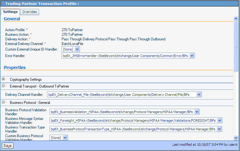
Note –
If the Unique ID handler is not selected, or if the message itself does not contain the Unique ID field (it is an optional field), random numbers are generated for the message Unique IDs. Third-party defined Unique IDs are not supported.
Configuring Transports
Table 6–2 lists the Transports parameter override values you must enter to configure B2B Host Configuration ⇒ envA_HIPAA ⇒ Transports ⇒ BatchLocalFile.
Table 6–2 Overrides for Atlanta B2B Host Configuration ⇒ … ⇒ BatchLocalFile|
Category |
Parameter |
Override Value |
|---|---|---|
|
Outbound ToPartner |
TargetDirectoryName |
C:\temp\eXchange\Sample\HIPAA\Data\Atlanta |
|
Inbound FromPartner |
TargetFileName |
ToAtlanta_[a-zA-Z0-9_]*\.msg |
|
ACK - Outbound ToPartner |
TargetDirectoryName |
C:\temp\eXchange\Sample\HIPAA\Data\Atlanta |
|
ACK - Inbound FromPartner |
TargetFileName |
ToAtlanta_[a-zA-Z0-9_]*\.msg |
Table 6–3 lists the Transport parameter override values you must enter to configure B2b Host Configuration ⇒ envB_HIPAA ⇒ Transports ⇒ BatchLocalFile.
Table 6–3 Overrides for Berlin B2B Host Configuration ⇒ … ⇒ BatchLocalFile|
Category |
Parameter |
Override Value |
|---|---|---|
|
Outbound ToPartner |
TargetDirectoryName |
C:\temp\eXchange\Sample\HIPAA\Data\Berlin |
|
Inbound FromPartner |
TargetFileName |
ToBerlin_[a-zA-Z0-9_]*\.msg |
|
ACK - Outbound ToPartner |
TargetDirectoryName |
C:\temp\eXchange\Sample\HIPAA\Data\Berlin |
|
ACK - Inbound FromPartner |
TargetFileName |
ToBerlin_[a-zA-Z0-9_]*\.msg |
Running the Sample
See Running the Sample Scenario for information on how to complete the passing of data between the two TPs.
The results after running the sample scenario:
-
...\HIPAA\Data\Atlanta folder contains
-
one 270 message
-
one 997 message
-
two TA1 messages
-
-
...\HIPAA\Data\Berlin folder contains
-
one 271 message
-
one 997 message
-
two TA1 messages
-
Using Message Tracking
eXchange provides a special feature, Message Tracking, allowing you to monitor the status of messages as they are received and processed through eXchange and HIPAA PM.
Before You Begin
-
You must already have deployed the appropriate Projects’ Deployment Profiles for the sample scenario.
Note –The B2B Host Project is not deployed.
-
Your Oracle and LDAP systems for eXchange must already be running, and you must already have begun running both Logical Hosts before you can run Message Tracking.
-
The inbound and outbound scenarios for the sample must be running.
-
For Message Tracking to be useful, there must be one or more messages that have already been picked up by the current Logical Host’s Integration Server.
Accessing Message Tracking
This section explains how to access Message Tracking.
 To Access Message Tracking
-
Start a browser session.
-
Point your browser at the following URL:
http://logicalhost:port+1/objname
Where:
-
logicalhost: The host name or IP address of a Logical Host running your Project, that is, the current Logical Host.
-
port: The Web server connector port configured in your Integration Server. To discover this information, use Environment Explorer to open the current Logical Host. Right-click the Integration Server and select Properties. Open IS Configuration ⇒ Sections ⇒ Web Container ⇒ Web Server ⇒ Default Web Server; port is the value set for Connector Port. If you have several Web server configurations, check them also.
The default port-number value is 18001 for the first Integration Server in the first-created Logical Host. (or 28001 for the first Integration Server in the second-created Logical Host, and so on). For the sample scenario, use 18001 for Atlanta ( envA) and 28001 for Berlin ( envB).
-
objname: The name of the Message Tracking instance as it appears on the current Connectivity Map. For the sample scenario, this name is tracker.
Example: To access Message Tracking for the sample scenario, use the following URLs:
http://localhost:18001/tracker
Note –You can only use the same port number for different Message Tracking instances if they reside on different machines.
As stated previously, the sample must be running before you access Message Tracking, and messages must have been transported before any become accessible.
-
Message Tracking Window
When you first run Message Tracking, the Message Tracking window appears. After you perform a search, as necessary, in the window’s left pane, message information results appear in the right pane. See Figure 6–15.
Figure 6–15 Atlanta: Example Message Tracking Window
See the eXchange Integrator User’s Guide for information on how to use Message Tracking.
Interleaved Error Reports
The HIPAA PM Message Tracking feature also allows you to view interleaved error reports, that is, reports that show any error you wish to view, in its messaging context.
 To View Interleaved Reports
-
In the Message Tracking window, select a message with one or more errors..
-
Next to Interleaved Report, click Open.
The interleaved error report appears. See Figure 6–16.
Figure 6–16 Atlanta: Interleaved Error Report
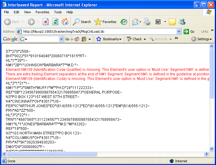
Any error appears in context, in red type. You may view interleaved error reports for inbound and outbound messages.
Note –Invalid messages may not be correlated.
- © 2010, Oracle Corporation and/or its affiliates
