| C H A P T E R 2 |
|
Preparing for Installation and Assembling the Cables |
This chapter provides instructions on preparing the Sun StorEdge S1 array for installation. This chapter also provides instructions on assembling the DC input power cables, for arrays that have DC power supplies.
This chapter is organized as follows:
The following table shows the order of the main installation tasks for the Sun StorEdge S1 array.
|
Assembling DC input cables (for arrays with DC power supplies) |
|

|
Caution - Before starting the installation, read the safety, regulatory, and compliance information in Appendix B and observe all applicable precautions. |
Before you install the Sun StorEdge S1 array, read Appendix B, and then do the following:
1. Read the following sections to make sure that you have the necessary hardware and equipment to install the array.
2. Read the most-recent version of the Sun StorEdge S1 Array Product Notes for updated product information.
You can find the latest product notes at:
http://www.sun.com/products-n-solutions/hardware/docs/Network_
Storage_Solutions/Workgroup/AC100_DC100
|
Note - The URL above is shown on multiple lines for reasons of space. Make sure the entire URL is entered into the browser without any breaks or spaces. |
3. Prepare the site for installation, including determining site power and sizing requirements.
Refer to Appendix A for power, size, and weight statistics.
You need one of the following host configurations to successfully install the array:
For LVD (Ultra 2/3) SCSI functionality, the host or the host bus adapter to which you connect your array must be capable of LVD (Ultra 2/3) SCSI speeds. If you connect the array to a wide or narrow SCSI-capable host bus adapter, the array performs at a lower speed.
If the arrays are installed on a LVD SCSI port on a host system or host bus adapter, up to four Sun StorEdge S1 arrays can be installed.
The following limitations apply to the number of arrays that can be installed in the the described situations:
For more information, see the following sections:
The total length of cable that can be used for a Sun StorEdge S1 array daisy chain depends on whether or not the host SCSI port or adapter is LVD SCSI or single-ended SCSI.
Follow these instructions to assemble the DC input power cable, which you use to connect the DC power supply to the DC power source.
|
Note - See Electrical Site Requirements for information on electrical site requirements. |
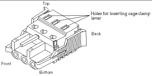
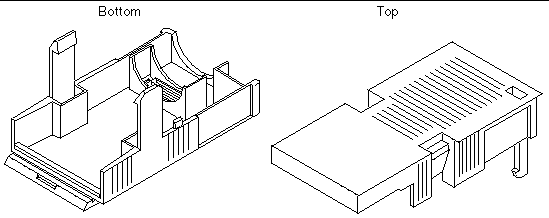
DC connection materials are provided with every array that includes a DC power supply. The following materials are used for assembling and connecting the power supply to the -48V DC power source:
 [ D ]
[ D ]
 [ D ]
[ D ]
|
Note - You can order another set of DC connection materials through Sun (part number X949A). |
Two DC power connectors are on the back of each DC version of the array (FIGURE 1-13). A close-up of a DC power connector is shown in the following figure.
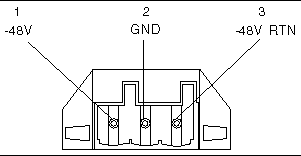
The contacts labeled from 1 through 3 from left to right in the above figure have the following characteristics:
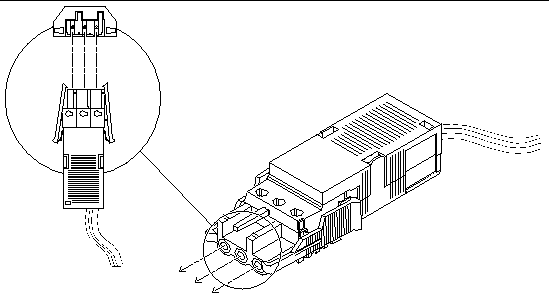
After you install the wires into the DC connector as described in To Assemble the DC Input Power Cable, you insert the assembled cable into the power connector on the array, as shown in FIGURE 2-5. (The procedure is described later in this manual, in To Connect the DC Power Cables.)
 [ D ]
[ D ]
1. Get a DC connector from the ship kit.
2. Verify that the circuit breakers are Off on the circuit that supplies power to the DC power source.

|
Caution - Make sure the circuit breakers are Off before proceeding with the next step. |
3. Locate the three wires coming from the DC power source.
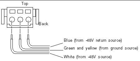
See the following table for the colors of each of the wires.
4. Strip 5/16 of an inch (8 millimeter) of insulation from each of the wires (FIGURE 2-6).

|
Caution - Do not strip more than 5/16 inch (8 millimeters) from each wire. Stripping more than that amount leaves uninsulated wire exposed from the DC connector after the assembly is complete. |

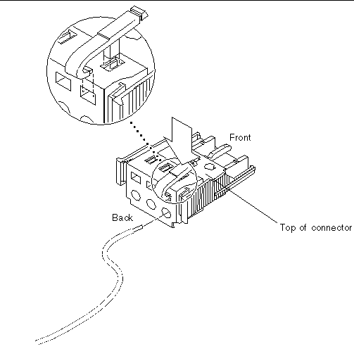
5. Use the cage clamp lever to open the cage clamp (FIGURE 2-7).
a. Insert the tip of the cage clamp lever into the rectangular hole directly above the hole in the DC connector where you want to insert the first wire.
The following illustration shows where to insert the lever when you are preparing to insert the white "Return" wire into the connector. (FIGURE 2-9 shows which colored wires go into which holes.)
 [ D ]
[ D ]
b. Press down on the cage clamp lever.
The cage clamp opens for this section of the DC connector.
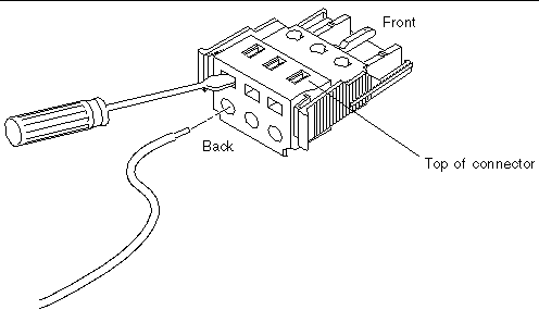
6. Alternately, open the DC connector cage clamp using a small flat-blade screwdriver (FIGURE 2-8).
The following illustration shows where to insert the lever to prepare to insert the white "Return" wire into the connector. (See FIGURE 2-9, which shows which wires go into which holes, if needed.)
a. Insert a small flat-blade screwdriver into the rectangular hole directly above the hole in the DC connector where you want to insert the first wire.
b. Press down on the screwdriver (FIGURE 2-8).
7. Feed the exposed section of each of the wires in turn into the appropriate hole in the DC connector.
FIGURE 2-9 shows which colored wire is inserted into each hole in the DC connector.
 [ D ]
[ D ]
8. Repeat Step 3 through Step 7 to create a second DC input power cable.
You connect the first DC input power cable to DC power source A and the second DC input power cable to DC power source B as described in Connecting and Disconnecting Power Cables.
1. Insert the cage clamp lever or a small screwdriver into the slot directly above the wire (FIGURE 2-7 and FIGURE 2-8), and press down.
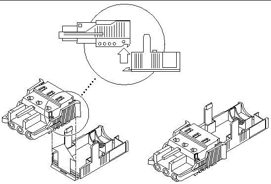
1. Insert the bottom portion of the strain relief housing into the notch on the bottom of the DC connector until it snaps into place as shown in FIGURE 2-10.
|
Note - Make sure the strain relief housing snaps firmly into place. You cannot complete the assembly correctly if the strain relief housing is not secure. |
 [ D ]
[ D ]
2. Route the three wires coming from the back of the DC connector across the bottom of the strain relief housing and out through the opening at the right of the strain relief housing (FIGURE 2-11).
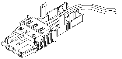
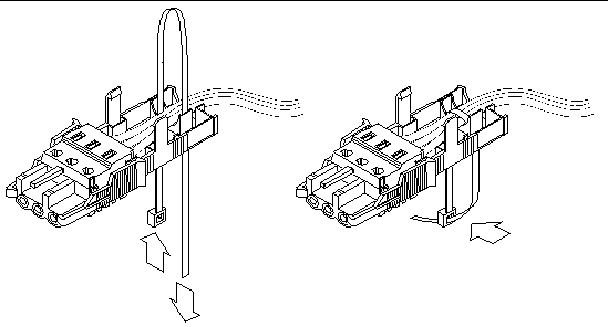
3. Insert the tie wrap up from the bottom into the opening on the left side of the wires in the strain relief housing (FIGURE 2-12).
One end of the tie wrap is straight and the other end has a rectangular connector, as shown in the following figure.
 [ D ]
[ D ]
4. Loop the tie wrap over the wires and back down through the strain relief housing, and then pull the flat end of the tie through the connector end until the slack in the tie is taken up, and the wires are tightly bound.
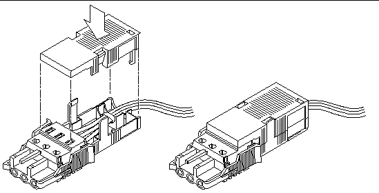
Lower the top portion of the strain relief housing (FIGURE 2-13) so that its front part covers the top rear holes on the DC connector and its three prongs are inserted into the corresponding holes on the housing's bottom.
 [ D ]
[ D ]
5. Push the top and bottom portions of the strain relief housing together until they snap into place.
As shown in FIGURE 2-13, the wires extend out of the back of the completed DC cable assembly.
Copyright © 2003, Sun Microsystems, Inc. All rights reserved.