| C H A P T E R 2 |
|
Hardware Installation and Removal |
The following instructions describe the tasks required to install the HBA. Refer to your system installation or service manual for detailed instructions.
This chapter contains the following topics:
The hardware installation process involves the following general steps:
1. Verifying the package contents
The following sections describe these steps in more detail.
|
Confirm that the HBA is shipped with the following document Accessing Documentation, 819-1209-xx.
|
1. Refer to your system installation or service manual to determine an appropriate ExpressModule slot in which to install the HBA.
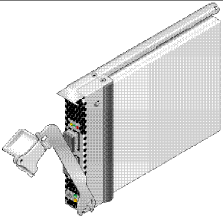
2. Press down the plastic tab to release the ExpressModule latch and pull the lever out until it is nearly perpendicular with the ExpressModule front panel.

3. Insert the HBA into its slot, being careful that the tooth on the bottom of the lever does not come in contact with the chassis sheet metal during insertion.
4. When the HBA is inserted nearly all the way into its slot, push the lever back into its fully closed position, allowing the lever tooth to insert the HBA fully into place.
|
|
Note - The HBA does not allow normal data transmission on an optical link unless it is connected to another similar or compatible Fibre Channel (FC) product (that is, multimode to multimode). |
Use multimode fiber-optic cable, intended for short-wave lasers, that adheres to the specifications in TABLE 2-1.
Follow these steps when attaching the optical cable:
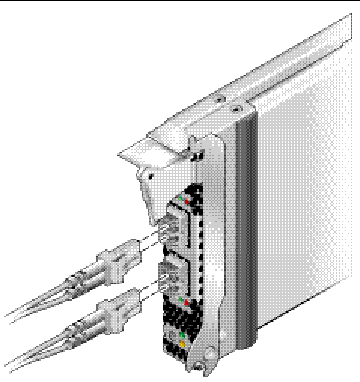
1. Connect the fiber-optic cable to an LC connector on the HBA (see FIGURE 2-2).

2. Connect the other end of the cable to the FC device.
After the optical cable is connected to the HBA, you are ready to apply power to the system. If power is already applied to the system, proceed to To Configure the HBA When Using Hot Plug.
|
1. Verify that the HBA is securely installed in the system.
2. Verify that the correct optical cable is attached.
3. Refer to your system installation or service manual to determine how to power up the system blade.
4. Observe the light-emitting diodes (LEDs) status for the POST results as shown in TABLE 2-2.
TABLE 2-2 summarizes LED indicator combinations. Refer to FIGURE 2-3 to determine the location of the LEDs. Each port has a corresponding set of LEDs that provide a visual indication of the operating state.
|
Yellow and amber flashing at the same time like a heart beat |

|
1. Locate the green Power indicator near the bottom of the HBA front panel.
2. If the green Power indicator is not illuminated, briefly press the Attention button near the bottom of the HBA front panel.
The green power LED should blink for approximately five seconds and then remain on, indicating that the HBA has been properly configured.
To cancel the operation, press the button again before it stops blinking.
|
 When the following screen is displayed during system power-on initiation, press Control-Q.
Then the following QLogic Fast!UTIL menu is displayed.
QLogic Fast!UTIL Select Host Adapter Adapter Type I/O Address Slot Bus Device Function QEM2462 E800 00 83 00 1 QEM2462 E400 00 83 00 0 |
|
1. Use the arrow key to select the HBA port that has devices connected, and press Enter.
The following QLogic Fast!UTIL menu is displayed.
2. Use the arrow key to select Scan Fibre Devices, and press Enter.
The following QLogic Fast!UTIL menu is displayed. In the example that follows, two ports of a storage array are attached to the selected port of the HBA through a switch.
3. To exit QLogic Fast!UTIL, press the Escape key, select Exit Fast!UTIL, and press Enter.
|
1. Use the cfgadm command to verify proper ExpressModule installation:
cfgadm
If the ExpressModule is properly installed and connected, you should see output similar to the following:
Ap_Id Type Receptacle Occupant Condition c3 fc connected configured ok c4 fc connected configured ok pcie5 fibre/hp connected configured ok |
2. If an ExpressModule adapter is shown as unconfigured or disconnected, use the cfgadm -c configure command to configure the adapter.
|
1. Use the cfgadm command to verify attached storage:
cfgadm -al
If the ExpressModule is properly installed and storage is connected properly, you should see output similar to that shown below. In this example, one port of an ExpressModule adapter is connected through a fabric switch to two ports of a disk array.
2. If an adapter is shown as unconfigured, use the cfgadm -c configure command to configure it.
The following instructions describe the tasks required to remove the HBA. Refer to your system installation or service manual for detailed ExpressModule adapter removal instructions.
The hardware removal process involves the following general steps:
1. Either halting the operating system and removing power from the server blade, or preparing the HBA for hot plug removal with one of the following:
|
 Press and release the Attention button near the bottom of the HBA front panel.
The green LED near the button should blink for approximately five seconds, indicating that the HBA is being prepared for removal.
Press the button again before the LED stops blinking to abort the operation.
Once the LED goes dark, the HBA can safely be removed.
|
If you want to remove the HBA without first halting the operating system and removing power from the associated server blade, you may first prepare it for removal as follows:
1. Use the cfgadm command to identify the HBA to be removed.
Ap_Id Type Receptacle Occupant Condition pcie5 fibre/hp connected configured ok pcie6 fibre/hp connected configured ok |
2. Use the cfgadm -c unconfigure command to unconfigure the attachment point ID (Ap_Id) for the HBA.
3. Use the cfgadm -c disconnect command to prepare the HBA for removal.
A flashing Power indicator LED indicates that the HBA is being prepared for removal. A dark Power indicator LED indicates that the HBA is ready to be removed.
|
Depress the ExpressModule latch to disengage the HBA, and then pull forward and down to dislodge it. You should then be able to easily remove the HBA.
Copyright © 2006, Sun Microsystems, Inc. All Rights Reserved.