| A P P E N D I X A |
 BIOS Screens
 |
This appendix describes how to view and or modify the BIOS Setup utility screens in the Sun Blade X6275 server module.
The following topics are covered in this appendix:
The BIOS Setup utility reports system information and can be used to configure the server BIOS settings. The Basic Input/Output System (BIOS) has a Setup utility stored in the BIOS flash memory.
The configured data is provided with context-sensitive help and is stored in the system's battery-backed CMOS RAM. If the configuration stored in the CMOS RAM is invalid, the BIOS settings default to the original state specified at the factory.
You can access BIOS configuration screens from the following interfaces:
To access BIOS configuration screens and change the system’s parameters:
1. Enter the BIOS Setup utility by pressing the F2 key while the system is performing the power-on self-test (POST). From a remote location, you can press CTRL-E.
When BIOS is started, the main BIOS Setup menu screen is displayed.
2. Highlight the field to be modified using the arrow and Tab keys.
Use the left and right arrow keys to move sequentially back and forth through the menu screens. Fields that can be reconfigured are displayed in color. All other fields are nonconfigurable.
3. Press Enter to select the field.
A dialog box shows the available options.
4. Modify the setup field and close the screen.
5. If you need to modify other setup parameters, use the arrow and Tab keys to navigate to the desired screen and menu item, and then repeat Step 1 through Step 4. Otherwise, go to Step 6.
6. Press and release the right arrow key until the Exit menu screen appears.
7. Follow the instructions on the Exit menu screen to save your changes and exit the Setup utility.
TABLE A-1 contains summary descriptions of the top-level BIOS setup screens.
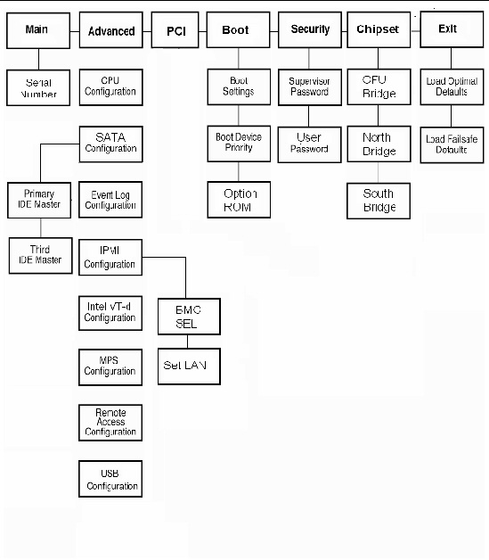
FIGURE A-1 summarizes the BIOS menu tree. See BIOS Setup Menu Screens for examples of each of these screens.
FIGURE A-1 BIOS Utility Menu Tree
The following figures show sample Sun Blade X6275 server module BIOS Setup utility screens.
| Note - The screens shown are examples. The version numbers and the screen items and selections shown are subject to change over the life of the product. |
All settings are set to the optimal default at startup.
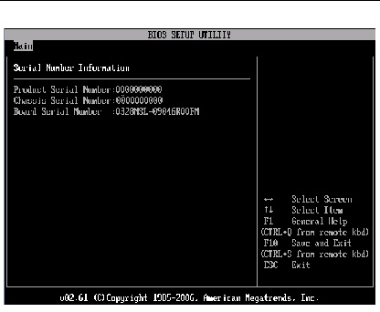
The BIOS Main screens provide general product information, including BIOS type, Processor type, memory, and time/date.
The Sun Blade X6275 server module has the following BIOS Main screens:
FIGURE A-2 BIOS Setup Utility: Main - System Overview
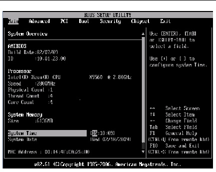
FIGURE A-3 BIOS Setup Utility: Main- Serial Number Information
The BIOS Advanced screens provide detailed configuration information for the CPU, SATA, IDE, event log, IPMI, Intel VT-d, MPS, remote access, USB, and other system configuration information.
| Note - The term BMC that might be displayed on some screens refers to the SP (service processor). |
The Sun Blade X6275 server module has the following BIOS Advanced screens:
FIGURE A-4 BIOS Setup Utility: Advanced
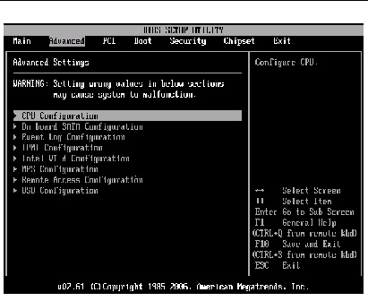
FIGURE A-5 BIOS Setup Utility: Advanced- CPU Configuration
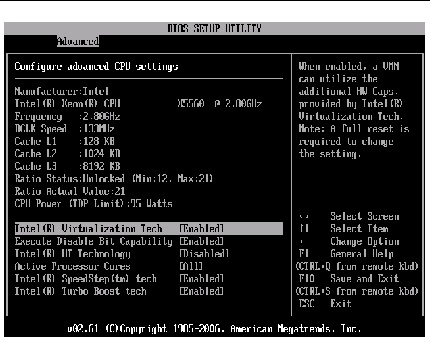
FIGURE A-6 BIOS Setup Utility: Advanced - SATA Settings
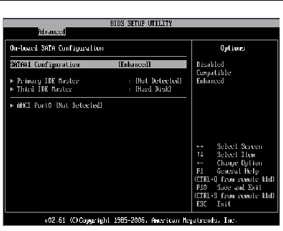
FIGURE A-7 BIOS Setup Utility: Advanced- IDE Configuration
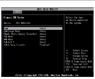
FIGURE A-8 BIOS Setup Utility: Advanced- Third IDE Master Configuration
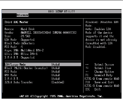
FIGURE A-9 BIOS Setup Utility: Advanced - Event Log
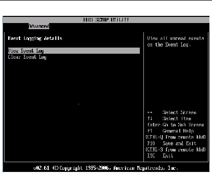
FIGURE A-10 BIOS Setup Utility: Advanced - View Event Log
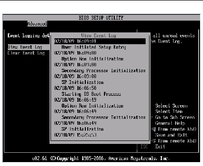
FIGURE A-11 BIOS Setup Utility: Advanced - Clear Event Log
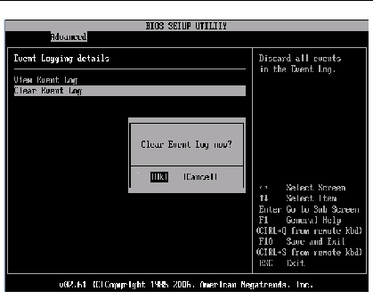
FIGURE A-12 BIOS Setup Utility: Advanced - IPMI Configuration (SP/BMC)
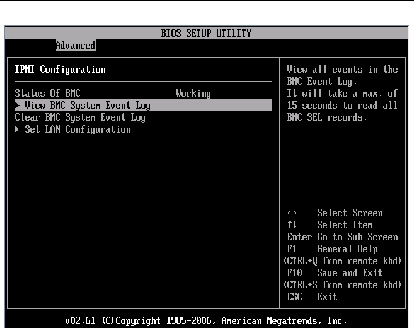
FIGURE A-13 BIOS Setup Utility: Advanced - IPMI - View BMC System Event Log (SEL)
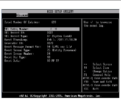
FIGURE A-14 BIOS Setup Utility: Advanced - IPMI - Clear BMC System Event Log
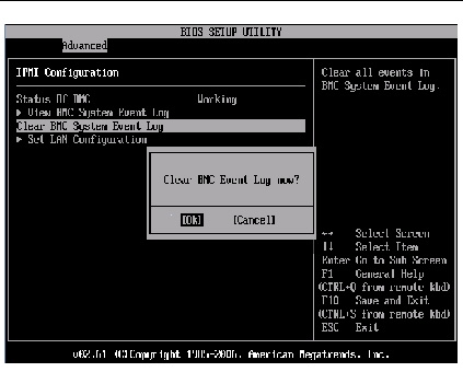
FIGURE A-15 BIOS Setup Utility: Advanced - IPMI - LAN Configuration -IP Assignment
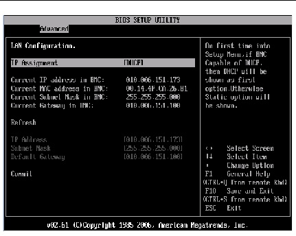
FIGURE A-16 BIOS Setup Utility: Advanced- Intel VT-d
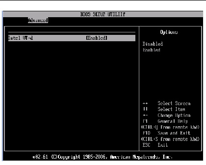
FIGURE A-17 BIOS Setup Utility: Advanced- MPS Configuration

FIGURE A-18 BIOS Setup Utility: Advanced- Remote Access Type and Parameters
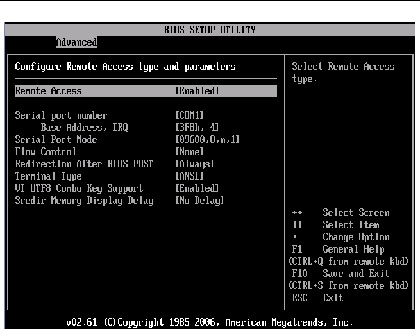
FIGURE A-19 BIOS Setup Utility: Advanced- USB Configuration
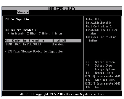
FIGURE A-20 BIOS Setup Utility: Advanced- USB Mass Storage Device Configuration
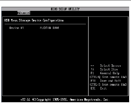
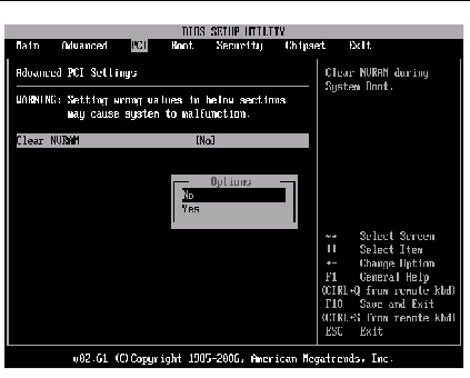
The BIOS PCI screens allow you to clear NVRAM during system boot. The Sun Blade X6275 server module has the following BIOS PCI screens:
FIGURE A-21 BIOS Setup Utility: PCI Settings
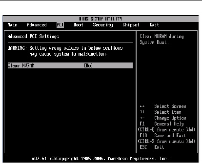
FIGURE A-22 BIOS Setup Utility: PCI Configuration - Clear NVRAM
The BIOS Boot screens allow you to configure the boot device priority (hard disk drives and the DVD-ROM drive). The Sun Blade X6275 server module has the following BIOS Boot screens:
FIGURE A-23 BIOS Setup Utility: Boot
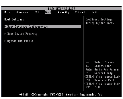
FIGURE A-24 BIOS Setup Utility: Boot Settings Configuration
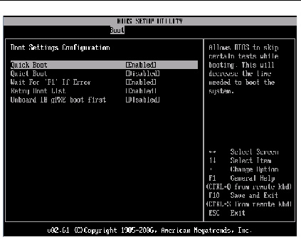
FIGURE A-25 BIOS Setup Utility: Boot Device Priority
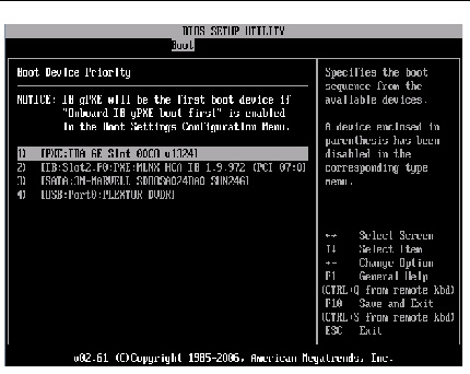
FIGURE A-26 BIOS Setup Utility: Boot Option ROM Enable
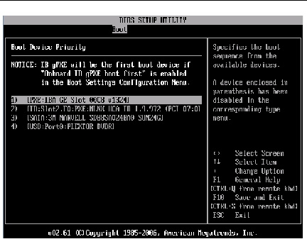
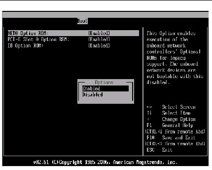
FIGURE A-27 BIOS Setup Utility: Boot Option ROM
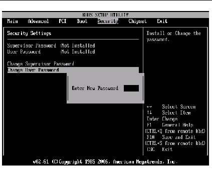
The BIOS Security screens allow you to set or change the supervisor and user passwords.
The Sun Blade X6275 server module has the following BIOS Security screens:
FIGURE A-28 BIOS Setup Utility: Security - Change Password
The BIOS Chipset screens allow you to configure chipset devices (if applicable).
The Sun Blade X6275 server module has the following BIOS Chipset screens:
FIGURE A-29 BIOS Setup Utility: Chipset
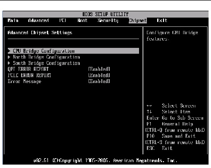
FIGURE A-30 BIOS Setup Utility: Chipset- CPU Bridge
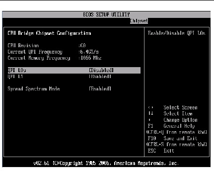
FIGURE A-31 BIOS Setup Utility: Server - Chipset - NorthBridge
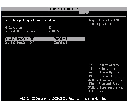
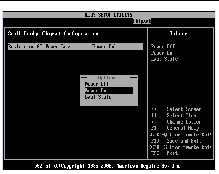
FIGURE A-32 BIOS Setup Utility: Server - Chipset - SouthBridge
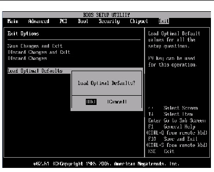
The BIOS Exit screens allow you to save changes and exit, discard changes and exit, discard changes, or load optimal or failsafe defaults.
The Oracle Sun Blade X6275 server module has the following BIOS Exit screens:
FIGURE A-33 BIOS Setup Utility: Exit
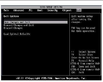
FIGURE A-34 BIOS Setup Utility: Exit - Save Configuration Changes
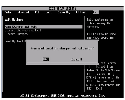
FIGURE A-35 BIOS Setup Utility: Exit - Discard Changes
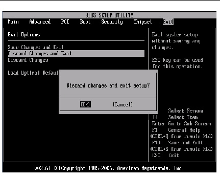
FIGURE A-36 BIOS Setup Utility: Exit - Discard Changes, Do Not Exit
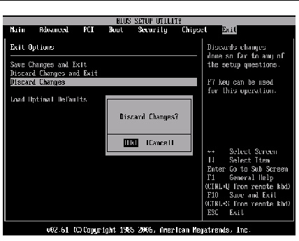
FIGURE A-37 BIOS Setup Utility: Exit - Load Optimal Defaults

Copyright © 2012, Oracle and/or its affiliates. All rights reserved.