| Sun Blade X6275 Server Module Installation Guide |
| C H A P T E R 3 |
|
Setting Up ILOM |
This chapter describes how to access the Sun Integrated Lights Out Manager (ILOM) software and how to configure an IP address for the Sun Blade X6275 server module Service Processor (SP).
This chapter contains the following topics:
The ILOM (Integrated Lights Out Manager) allows you to manage the system chassis using the CMM ILOM, and manage the Sun Blade X6275 server module nodes using the SP ILOM.
This section contains the following topics:
ILOM software provides a command-line interface (CLI) and a web browser user interface. For detailed ILOM information, refer to the Integrated Lights Out Manager documentation.
Each system chassis has its own service processor, called a Chassis Monitoring Module Integrated Lights Out Manager (CMM ILOM). CMM ILOM provides an Ethernet connection to the server module's service processor, and allows you to view and configure the Sun Blade X6275 server module's network information. See FIGURE 3-1.
Supported CMM ILOM versions are:
Refer to the system chassis documentation for more information. Go to http://docs.sun.com/app/docs/prod/blade.srvr#hic.
FIGURE 3-1 CMM ILOM Web Interface Page
The Sun Blade X6275 server module includes two service processor (SP) ILOMs that reside on a separate board. Each node has a dedicated SP.
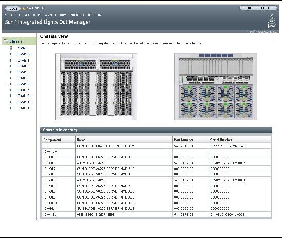
You can use the ILOM built-in system management software to monitor and manage the components installed in your system chassis and server modules. See FIGURE 3-2.
For detailed ILOM information, refer to the Integrated Lights Out Manager documentation.
FIGURE 3-2 SP ILOM Web Interface Page (via CMM ILOM 3.0 system)

TABLE 3-1 summarizes how to set up ILOM and configure an IP address on the server module SP.
|
Install the server module in the system chassis as described in and Chapter 2 of this guide. Note - For CMM ILOM 2.0.3.13 systems, a Sun Blade X6275 server module must be inserted into the system chassis before you power on the chassis. If the blade is not inside the chassis before you power on, ILOM does not recognize node 1. For ILOM 3.0 systems, this requirement does not apply. |
||
|
Ensure that the Sun Blade X6275 server module has standby power. |
||
|
If you are using ILOM CLI commands and you do not know the ILOM’s IP address, see Displaying the Service Processor’s (ILOM) IP Address to find the CMM SP ILOM’s IP address using the CMM ILOM. |
||
|
If you are using ILOM CLI commands and you do not know the ILOM’s IP address, see Displaying the Service Processor’s (ILOM) IP Address to find the Sun Blade X6275 server module SP ILOM’s IP address using the CMM ILOM. |
||
|
Choose one of the following methods to establish a connection with the Sun Blade X6275 server module SP ILOM. Note - Recommended. The remote connection chassis Ethernet ports provide both the CLI and the web browser user interface method to connect to ILOM.
Note - For more information about how to attach a CMM management network cable, and attaching other cables or devices to a CMM, refer to the system chassis documentation. |
||
|
To configure an IP address in SP ILOM, you must log in to ILOM with an administrative account, for Node 0 or Node 1. A preconfigured administrator account is shipped on each node on the server module. This administrative account includes built-in administrative privileges (read and write access) to all SP features and commands. The user name is root and the password is changeme. Tip - It is highly recommended that you change the password after initial setup, for security reasons. For more information about ILOM’s user accounts, refer to the Integrated Lights Out Manager documentation. |
||
|
You might need to obtain additional information about ILOM, if applicable. For more information about configuring or modifying an IP address in ILOM, refer to the Integrated Lights Out Manager documentation. |
Use the following CLI procedure to display the ILOM’s network configuration, including the IP address of the ILOM SP, using the CMM ILOM.
| Note - You can also obtain node SP IP addresses from Web interface of the CMM. |
This procedure also verifies that the ILOM is working correctly and that you can access it through the CMM ILOM.
2. Log in to the CMM ILOM CLI.
3. Type one of the following commands, depending on the CMM ILOM revision:
where BL0 represents blade 0 and NODE1 is node 1.
To view the target blade and node, you must specify the number of the blade in which the server module is installed, and the node number.
The CMM ILOM displays information about the server module, including its IP address and MAC address. The following example shows Blade 0, Node 1, server module information:
where BL14 represents node 1 installed in slot 3.
To specify the target CMM or blade, you must specify the number of the slot in which the module is installed.
Each Sun Blade 6048 chassis shelf has 24 nodes maximum. Blade nodes are numbered from 0 to 23. CMM Nodes 0 to 11 are blade node 0 and named BL0-BL11. CMM nodes 12 to 23 are blade node 1 and named BL12-BL23. For a Sun Blade 6048 chassis, the nodes display as:
0 |
BL0 |
BL1 |
BL2 |
BL3 |
BL4 |
BL5 |
BL6 |
BL7 |
BL8 |
BL9 |
BL10 |
BL11 |
1 |
BL12 |
BL13 |
BL14 |
BL15 |
BL16 |
BL17 |
BL18 |
BL19 |
BL20 |
BL21 |
BL22 |
BL23 |
The CMM ILOM displays information about the server module, including its IP address and MAC address. For example:
4. Proceed to Accessing SP ILOM.
Choose one of the following procedures to log in to the SP ILOM:
|
To log in to the SP ILOM from an Ethernet connection using the CLI command line interface:
1. Obtain the ILOM IP address.
If you do not know the ILOM’s IP address, see Displaying the Service Processor’s (ILOM) IP Address to find the ILOM’s IP address, using the CMM ILOM.
2. Open a new terminal window, as required.
3. Log in to SP ILOM using secure shell (SSH) session.
Type the administrator account user name (root), the password (changeme), and the server module SP IP address.
For example: ssh root@192.168.25.25
You are now logged in to the SP ILOM.
Refer to the ILOM documentation for more information on how to use the CLI interface to configure the ILOM.
|
| Note - To improve response times, disable the browser proxy server (if used). |
To log in to the SP ILOM from an Ethernet connection using the web browser user interface:
1. Obtain the SP ILOM IP address for the node.
If you do not know the node’s ILOM IP address, see Displaying the Service Processor’s (ILOM) IP Address to find the ILOM’s IP address using the CMM ILOM.
2. To log in to the web interface, type the IP address of ILOM into your web browser.
The web interface Login page appears.

3. Type your user name and password.
The web interface Versions page appears.

You are now logged in to the SP ILOM.
Refer to the ILOM documentation for more information on how to use the web interface to configure the ILOM.
|
You will need a dongle cable. The dongle cable might be shipped with the Sun Blade chassis.
To log in to the ILOM from a serial console connection:
1. Use a dongle cable to connect a serial console to a UCP port on the front of the server module. There are two UCP ports, one for each node SP connection.
For more information, refer to the Sun Blade X6275 Server Module Service Manual.
2. Verify that your serial console connection to the Sun Blade X6275 server module is secure and operational.
3. Ensure that the following serial communication settings are configured.
4. Press Enter to establish a connection between your serial console and ILOM.
A login prompt to ILOM appears.
5. Log in to the ILOM CLI using an administrator account. Type a user name and password for the administrator account.
You are now logged in to the SP ILOM.
Refer to the ILOM documentation for more information on how to use the CLI interface to configure the ILOM.
You can configure a static or a dynamic IP address for SP Network Configuration.
Choose one of the following procedures:
|
DHCP is enabled in the factory-default configuration. By default, the SP uses a Dynamic Host Configuration Protocol (DHCP) server for network configuration.
To configure SP networks with a DHCP server:
1. Verify that an Ethernet cable is connected to the Ethernet port (NET MGT) port on the CMM.
2. Obtain the CMM ILOM IP address.
If you do not know the ILOM’s IP address, see Displaying the Service Processor’s (ILOM) IP Address to find the ILOM’s IP address using the CMM ILOM.
3. Log in to CMM ILOM. Choose one of the following procedures:
4. Obtain the DHCP IP address assigned to the server module SP.
Choose one of the following procedures, to view the dynamic server module IP address that was assigned:
Type: show /CH/BL0/NODE1/SP/network
where BL0 represents the blade slot 0, node 1.
where BL0 represents node 0 installed in slot BL0.
To specify the target CMM or blade, you must specify the number of the slot in which the module is installed. Blade nodes range from 0 to 23. Each shelf has 24 nodes, numbered BL0 to BL23. Slots BL0 to BL11 are node 0. Slots BL12 to BL23 are node 1.
5. To configure the SP to use DHCP, type:
-> cd  /CH/BL4/NODE1/SP/network
-> set pendingipdiscovery=dhcp
-> set commitpending=true
6. To log out of ILOM, type exit.
Refer to the ILOM documentation for more information on how to use the ILOM CLI interface.
You can now load the operating system. See About Installing a Supported OS.
|
If you plan to assign static IP addresses to a server SP, do the following procedure for each node:
1. Verify that an Ethernet cable is connected to the Ethernet port (NET MGT) port on the CMM.
2. Obtain the CMM ILOM IP address.
If you do not know the ILOM’s IP address, see Displaying the Service Processor’s (ILOM) IP Address to find the ILOM’s IP address using the CMM ILOM.
3. Log in to CMM ILOM. Choose one of the following procedures:
4. Configure a static Ethernet configuration.
Use your own addresses in place of the examples below:
-> cd  /CH/BL4/NODE1/SP/network
-> set pendingipaddress=129.144.82.26
-> set pendingipnetmask=255.255.255.0
-> set pendingipgateway=129.144.82.254
-> set pendingipdiscovery=static
-> set commitpending=true
5. To log out of ILOM, type exit.
Refer to the ILOM documentation for more information on how to use the ILOM CLI interface.
You can now load the operating system. See About Installing a Supported OS.
Choose one of the following methods to install a supported Operating System (OS) on a Sun Blade X6275 server module:
Refer to the Sun Blade X6275 Server Module Linux OS Installation Guide or Sun Blade X6275 Server Module Windows OS Installation Guide for more detailed instructions and supported OSes for operating system installation.
The Sun Blade X6275 server module supports one flash module (FMod) per node that can install and boot a supported operating system. You can use flash modules to install an operating system locally.
To install flash modules, refer to the Sun Blade X6275 Server Module Service Manual.
The Sun Blade X6275 server module has one internal USB port per node on the back of the motherboard. You must remove the blade from the chassis to access the USB ports.
When a USB flash disk is present, it appears as a disk device, and you can install a supported operating system on it.
To install a USB flash disk, refer to the Sun Blade X6275 Server Module Service Manual.
USB flash disks with standard USB 2.0 interfaces can be obtained from third-party sources. Each Sun Blade X6275 server module can use two USB flash disks, one per node. The USB flash disks must be no larger than 2.7 mm wide and 32.0 mm long. See FIGURE 3-3.
FIGURE 3-3 USB Flash Disk Dimensions

| Sun Blade X6275 Server Module Installation Guide | 820-6977-11 |
Copyright © 2009 Sun Microsystems, Inc. All rights reserved.
 Log In to SP ILOM Using the CLI
