| Sun Blade X6275 Server Module Installation Guide |
| C H A P T E R 2 |
|
Installing and Powering On the Sun Blade X6275 Server Module |
This chapter contains the following topic.
To install the Sun Blade X6275 server module into a Sun Blade 6048 or Sun Blade 6000 modular system chassis:
1. Perform all steps and fufill all requirements in .
2. Attach a grounded antistatic wrist strap, foot strap, or equivalent safety equipment to prevent electrostatic discharge (ESD) when you install the Sun Blade server module into the system chassis.
3. Locate and remove the relevant server module filler panel.
Pull the lever out to the open position and eject the filler panel.
Keep the filler panel for later use.
4. Verify a steady on green light on the Chassis OK power LED. The light indicates that the system chassis is powered on.
If the Chassis OK green light is steady on, then the Sun Blade 6048 or Sun Blade 6000 modular system chassis has power and is operational. If the chassis has not been powered on, refer to the system chassis documentation to power on the system chassis.
5. Check the rear of the system chassis to ensure that all power cords have been installed and connected to the mains.
6. Check that full power is available.
Verify that the system chassis Power Supply AC OK and DC OK LEDs illuminate steady green.
7. Position the server module vertically so that the ejectors are on the right and extend outward.
FIGURE 2-1 shows the server module being inserted into the Sun Blade 6048 or Sun Blade 6000 modular system. Your chassis might differ.
8. Push the server module into the slot until the server module stops and is flush with the chassis. See FIGURE 2-1 [1].
FIGURE 2-1 Inserting the Server Module Into the Chassis (Sun Blade 6048 Modular System shown)

9. Lock the server module into the chassis. Rotate the top ejector down while rotating the bottom ejector up until they both latch into place.
See FIGURE 2-1 [2]. The server module is now locked in the chassis.
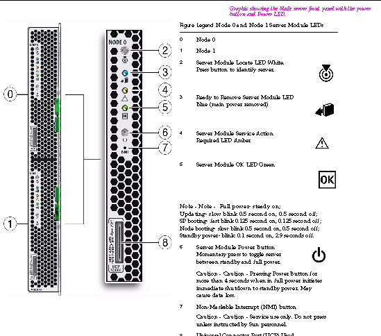
10. Verify that the server module’s LEDs illuminate as follows. See FIGURE 2-2.
a. After you plug in the blade, all four server module LEDs (on each Node) blink three times. When the front panel lights on the server module blink three times after the blade is inserted, then the blade has been powered on, and the SP boot process starts.
b. The server module green OK LEDs on Node 0 and Node 1 illuminate a fast blink. fast blink indicates that the server module SP is booting (0.125 seconds on, 0.125 seconds off).
c. The server module green OK LEDs on Node 0 and Node 1 illuminate a slow blink. slow blink indicates that a server module node is booting (0.5 seconds on, 0.5 seconds off).
d. A steady on green light on the Node 0 and Node 1 server module green OK LEDs indicates that the boot cycle is complete and the server module nodes are ready.
| Note - If the blade is in standby power mode, the two server module green OK LEDs blink briefly once every 3 seconds. Refer to the Sun Blade X6275 Server Module Diagnostics Guide. |
| Tip - For additional LED information, server module removal, power procedures, and front panel cable connection information, refer to the Sun Blade X6275 Server Module Service Manual. |
FIGURE 2-2 Sun Blade X6275 Server Module Front Panel LEDs
The physical installation is complete.
11. Set up the ILOM SP on each node, 0 and 1. See Setting Up ILOM.
| Sun Blade X6275 Server Module Installation Guide | 820-6977-11 |
Copyright © 2009 Sun Microsystems, Inc. All rights reserved.
