| C H A P T E R 8 |
|
Troubleshooting Your Array |
This chapter covers the following maintenance and troubleshooting topics:
For more troubleshooting tips, refer to the release notes for your array. See for more information.
Monitoring conditions at different points within the array enables you to avoid problems before they occur. Cooling element, temperature, voltage, and power sensors are located at key points in the enclosure. The Sun StorEdge SCSI Enclosure Services (SES) processor monitors the status of these sensors. Refer to the Sun StorEdge 3000 RAID Firmware User's Guide for details.
The following tables describe each element and its sensors.
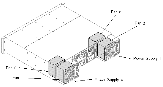
Each Sun StorEdge 3510 FC array and Sun StorEdge 3511 SATA array has two fully redundant power supplies, with load sharing capabilities. The sensors monitor the voltage, temperature, and fans in each power supply.
There are two fans in each power supply module. The normal range for fan speed is 4000 to 6000 RPM. Cooling element failure occurs when a fan's speed drops below 4000 RPM.
Extreme high and low temperatures can cause significant damage if they go unnoticed. There are twelve temperature sensors at key points in the enclosure.
Voltage sensors make sure that the array's voltage is within normal ranges. The voltage components differ for the Sun StorEdge 3510 FC array and the Sun StorEdge 3511 SATA array. The following tables describe each voltage sensor.
|
Upper I/O Module (1.812V)[1] |
|||
|
Lower I/O Module (1.812V)1 |
|||
An audible alarm indicates that either a component in the array has failed or a specific controller event has occurred. Error conditions and controller events are reported by event messages and event logs. Component failures are also indicated by LED activity on the array.
|
Note - It is important to know the cause of the error condition because how you silence the alarm depends on the cause of the alarm. |
To silence the alarm, perform the following steps:
1. Check the error messages, event logs, and LED activity to determine the cause of the alarm.
Component event messages include but are not limited to the following:
See Appendix C for more information about component alarms.
Controller event messages include but are not limited to the following:
Refer to the "Event Messages" appendix in the Sun StorEdge 3000 Family RAID Firmware User's Guide for more information about controller events.
2. Depending on whether the cause of the alarm is a failed component or a controller event and which application you are using, silence the alarm as specified in the following table.
Pushing the Reset button has no effect on controller event alarms and muting the beeper has no effect on failed component alarms.
By default, all RAID arrays are preconfigured with one or two logical drives. For a logical drive to be visible to the host server, its partitions must be mapped to host LUNs. To make the mapped LUNs visible to a specific host, perform any steps required for your operating system. For host-specific information about different operating systems, see:
Controller failure symptoms are as follows:
A "Redundant Controller Failure Detected" alert message is displayed and written to the event log.
If one controller in the redundant controller configuration fails, the surviving controller takes over for the failed controller. The primary controller state will be held by the surviving controller regardless of the serial number until redundancy is restored.
The surviving controller disables and disconnects from its counterpart while gaining access to all the signal paths. It then manages the ensuing event notifications and takes over all processes. It remains the primary controller regardless of its original status, and any replacement controller afterward assumes the role of secondary controller.
The failover and failback processes are completely transparent to the host.
|
Note - If the surviving controller is removed and the failed controller is left in the system, and the system is power-cycled, the failed controller can become primary and write stale data to disk. |
Controllers are hot-swappable if you are using a redundant configuration, and replacing a failed unit takes only a few minutes. Since the I/O connections are on the controllers, you might experience some unavailability between the times when the failed controller is removed and a new one is installed in its place.
To maintain your redundant controller configuration, replace the failed controller as soon as possible. For details, refer to Sun StorEdge 3000 Family FRU Installation Guide.
|
Note - When the drives cannot be identified by the controller, either due to disk channel errors or powering up in the wrong sequence, the drive state will change to USED with all logical drives in a FATAL FAIL state. To recover from this state, the condition that caused the loss of access to the disk drives must be resolved and a power cycle of the system is required. The FATAL FAIL state remains following the power cycle and requires user intervention to clear. For details regarding the FATAL FAIL state, see Section 8.5, Recovering From Fatal Drive Failure. |
With a RAID array system, your system is protected with the RAID parity drive and a global spare or spares.
A Fatal Fail occurs when more drives fail than your RAID redundancy can accommodate. The redundancy of your RAID array depends on your configuration. In a RAID 3 or RAID 5 configuration, two or more drives must fail for a FATAL FAIL status. In a RAID 1 configuration, you can lose multiple drives without fatal failure if all the failed drives reside on one side of a mirrored pair.
It might be possible to recover the RAID array from a Fatal Fail. However, it might be impossible to do a full data recovery, depending on the circumstances of the failure. Recovering from a Fatal Fail requires reusing the drives that report as failed. It is important to check your recovered data using the data application or host-based tools following a Fatal Fail recovery.
It is rare for two or more drives to fail at the same time. To minimize the chance of this happening, regular RAID integrity checks should be performed. For RAID 3 and RAID 5, this can be done using the array console's "regenerate Parity" option, or using the Sun StorEdge CLI command-line utility check parity. Refer to the Sun StorEdge 3000 Family RAID Firmware User's Guide for details on the "regenerate Parity" option. Refer to the Sun StorEdge 3000 Family CLI User's Guide for details on the check parity command line utility.
If a multiple drive failure has occurred, it might be possible to recover by performing the following steps:
1. Discontinue all I/O activity immediately.
2. To cancel the beeping alarm, from the RAID firmware Main Menu, choose "system Functions  Mute beeper".
See Section 8.2, Silencing Audible Alarms for more information about silencing audible alarms.
3. Physically check that all the drives are firmly seated in the array and that none have been partially or completely removed.
4. In the RAID firmware Main Menu, choose "view and edit Logical drives," and look for:
Status: FATAL FAIL (two or more failed drives)
5. Select the logical drive, press Return, and choose "view scsi drives."
If two physical drives fail, one drive has a BAD status and one drive has a MISSING status.
6. Unassign any global or local spare drives.
From the RAID firmware Main Menu, choose "system Functions  Reset controller" and choose Yes when prompted.
8. When the system comes back up, clear the FATAL FAIL state.
a. From the RAID firmware Main Menu, choose "view and edit Logical drives."
b. Select the logical drive with the FATAL FAIL status and press Enter.
d. Choose Yes when the "Back to degraded?" prompt is displayed.
|
Note - The prompt is "Back to normal?" for RAID 0 configurations. |
After clearing the FATAL FAIL, the status changes to DRV FAILED.
9. If the status is still FATAL FAIL, you might have lost all data on the logical drive, and it might be necessary to re-create the logical drive.
Proceed with the following procedures:
Refer to the Sun StorEdge 3000 Family RAID Firmware User's Guide for more information.
b. Create a new logical drive.
Refer to the Sun StorEdge 3000 Family RAID Firmware User's Guide for more information.
10. If the logical drive has changed to "degraded," run fsck(1M).
11. After fsck(1M) completes successfully, rebuild the logical drive.
|
Note - The logical drive can be rebuilt with a local or a global spare drive. If no local or global spare is assigned, the logical drive will be rebuilt with the remaining BAD drive. |
a. If you unassigned any local or global spare drives in Step 6, reassign them now.
The rebuild will begin automatically.
12. If no spare drives are available, perform the following steps.
a. From the RAID firmware Main Menu, choose "view and edit Logical drives."
b. Select the logical drive that has the status DRV FAILED.
c. Choose "Rebuild logical drive," and then choose Yes to rebuild the logical drive.
The rebuilding progress is displayed on the screen. A notification message informs you when the process is complete.
Rebuilding the logical drive restores the RAID integrity to a self-consistent state. This does not guarantee that the data has not been corrupted. All possible application checks should be performed to ensure that the data is not corrupted before it is used for business or production purposes.
For additional troubleshooting tips, refer to the release notes for your array.
The Reset push button serves two purposes:
To test that the LEDs work, use a paper clip to press and hold the Reset button for 5 seconds. All the LEDs should change from green to amber when you perform this test. Any LED that fails to light indicates a problem with the LED. When you release the Reset button, the LEDs return to their initial state. See Section 6.2, Front Panel LEDs for more information.
To silence audible alarms that are caused by component failures, use a paper clip to push the Reset button. See Section 8.2, Silencing Audible Alarms for more information about silencing audible alarms.
This section provides troubleshooting flowcharts to illustrate common troubleshooting methods.
The flowcharts included in this section are:
For the JBOD and expansion unit flowchart, see Section B.11, Troubleshooting Sun StorEdge 3510 FC JBOD Arrays.
For overview information about LEDs, see Chapter 6.
For information about replacing modules, refer to the Sun StorEdge 3000 Family FRU Installation Guide.
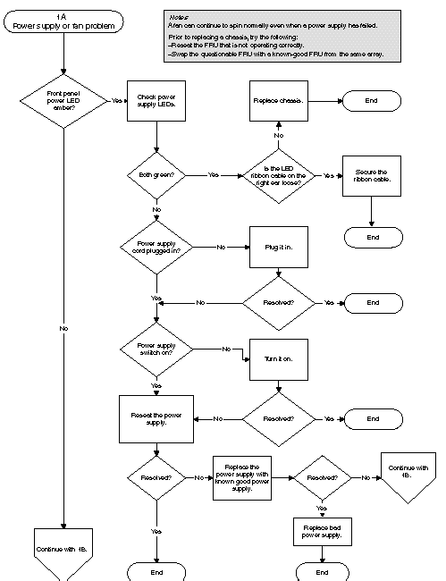
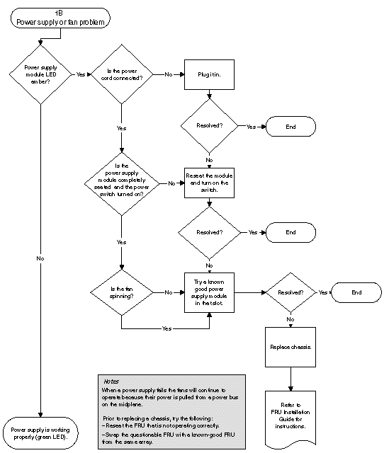
The following flowchart provides troubleshooting procedures for the power supply and fan module.
Before you perform the drive LED troubleshooting procedures, you might want to use the firmware application to identify a failed drive. Refer to the Sun StorEdge 3000 Family RAID Firmware User's Guide for more details.
For overview information about drive LEDs and how they work, see Section 6.2, Front Panel LEDs.
You can check physical drive parameters using the firmware application. From the RAID firmware Main Menu, choose "view and edit Drives." For more information about the firmware application, refer to the Sun StorEdge 3000 Family RAID Firmware User's Guide for your array.

|
Caution - To prevent any possible data loss, back up user data to another storage device prior to replacing a disk drive. |

|
Caution - When you replace drives, make sure that all I/O is stopped. |
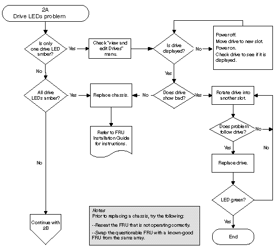
The following flowchart provides troubleshooting procedures for the FC drive LEDs.
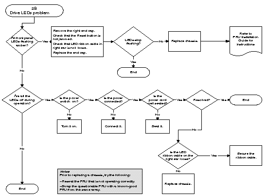
For more information about checking and replacing drive modules, refer to the Sun StorEdge 3000 Family FRU Installation Guide.
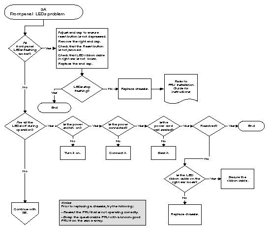
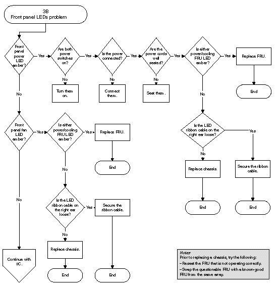
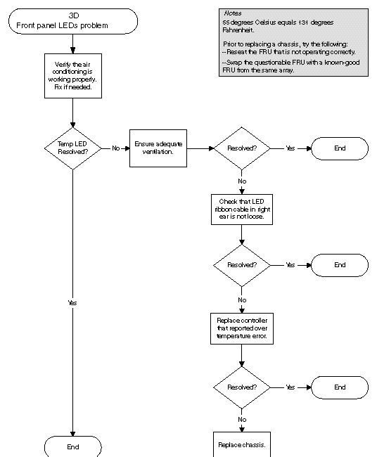
The following flowchart provides troubleshooting procedures for the Sun StorEdge 3510 FC array and Sun StorEdge 3511 SATA array front panel LEDs.
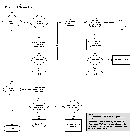
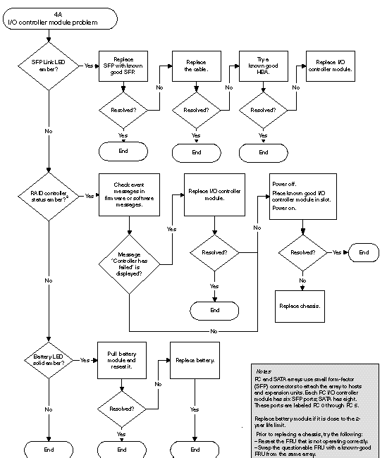
The following flowchart provides troubleshooting procedures for the I/O controller module.
Copyright © 2004, Sun Microsystems, Inc. All rights reserved.