| C H A P T E R 9 |
|
FC and SATA Module FRUs |
This chapter provides instructions for removing and installing field-replaceable units (FRUs) in Sun StorEdge 3510 FC and Sun StorEdge 3511 SATA arrays.
Topics covered in this chapter are:
Be sure to follow Section 1.2, Static Electricity Precautions.
Keep the array powered on, and be sure that the connected hosts are inactive during this procedure.
1. Turn the thumbscrews on the left and right sides of an I/O expansion module counterclockwise until the thumbscrews are disengaged from the chassis.
2. Grasp the handle and pull out the I/O expansion module.
Keep the array powered on, and be sure that the connected hosts are inactive during this procedure.
1. Slide the I/O expansion module into the chassis until the module is firmly seated in the backplane, and the module's front panel is flush with the chassis.

|
Caution - Be sure that the I/O expansion module is properly inserted in the guide rails of the array. |
2. Turn the thumbscrews on the left and right sides of the I/O expansion module clockwise until the thumbscrews are finger-tight to secure the module.
|
Note - To ensure that a thumbscrew is finger-tight, tighten it with a screwdriver and then loosen the thumbscrew counterclockwise a quarter turn. |
When you power on your array, if you hear an audible alarm and see a blinking amber Event light on the front of your array, the SES firmware or its associated PLD code in the new controller has a version that is different from the code in the other I/O controller in your array. To solve this mismatch, see Section 6.3.4, SES Firmware Update Sometimes Required with I/O Controller Module Replacements.
|
Note - The beep code that identifies an SES or PLD firmware mismatch is the repeating Morse code letter "R" (dot dash dot). |
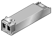
Fibre Channel arrays use small form-factor (SFP) transceivers to attach the array to hosts and expansion units.
Sun StorEdge 3510 FC array I/O controller modules have six SFP ports, as shown in the lower row of ports in FIGURE 9-1. These ports are labeled FC0 through FC5. Sun StorEdge 3511 SATA array I/O controller modules have eight SFP ports, as shown in FIGURE 9-2. SFP ports on the Sun StorEdge 3511 SATA array are also labeled FC0 through FC5.


Each Sun StorEdge 3510 FC I/O expansion module has two SFP ports. Sun StorEdge 3511 SATA I/O expansion modules have four SFP ports. On both Sun StorEdge 3510 FC and Sun StorEdge 3511 SATA I/O expansion modules, these ports are labeled Loop A or Loop B.
To install an SFP in an SFP port:
1. Slide the SFP into the SFP port until it locks into place.
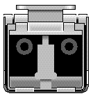
2. Plug one end of a Fibre Channel cable into the duplex jack at the end of the SFP, as shown in FIGURE 9-4.
3. Plug the other end of the Fibre Channel cable into a server or into an FC expansion unit.
|
Note - To remove an SFP, make sure that no cable is connected to it and then slide it out from the port. |
The chassis (box) FRU for the Sun StorEdge 3510 FC and Sun StorEdge 3511 SATA arrays includes a chassis, its drive midplane, and its backplane. This product is ordered to replace a box that has been damaged or whose midplane or backplane has been damaged.
To make a fully functional array, you must add the following parts from the replaced array:
To install the individual modules, use the replacement instructions provided in this guide.
To configure the array, refer to the installation manual for your array. The installation manuals are located on the Sun StorEdge 3000 Family Documentation CD. Manuals for both the Sun StorEdge 3510 FC and Sun StorEdge 3511 SATA arrays are also located on the product web sites.
To replace the chassis frame of an existing RAID array or expansion unit, perform the following steps.

|
Caution - Connected hosts must be inactive during this replacement procedure. |
|
Note - Be sure to follow Section 1.2, Static Electricity Precautions for all procedures. |
1. Connect to the firmware application via the serial interface (tip for Solaris/Linux) or via telnet.
2. If the defective array is a RAID array:
a. From the RAID firmware Main Menu, choose "view and edit Configuration parameters  Controller Parameters."
b. Write down the Controller Unique Identifier (hex) - value.
3. If the defective array is a RAID array, stop all I/O activity and shut down the RAID controller:
 Shutdown Controller." Then choose Yes to confirm.
4. Power off both power supply modules on the defective array.
5. Clearly label all FC cables attached to the I/O controller module.
6. Write down the defective array's cabling configuration.
7. Remove all FC cables attached to the I/O controller module.
8. If the defective array is a RAID array, remove all serial, Ethernet, and power cables connected to the I/O controller modules.
9. Label each disk drive with its disk slot position in the array.
10. Remove the I/O controller modules, power supply modules, and disk drives from the defective array.
Make sure you place the component on a flat surface that is not susceptible to electrostatic discharge.
11. Remove the defective chassis.
12. Obtain the replacement chassis.
13. Reinstall all previously removed FRUs in their original positions in the replacement chassis.
14. Reinstall all FC, serial, Ethernet, and power cables in their original positions.
15. Power on both power supply modules.
16. If the replacement chassis is an expansion unit or JBOD, refer to your installation manual to configure it.
17. If the replacement chassis is a RAID array, proceed with the following steps:
a. Connect to the array console menu interface via the serial interface (tip for Solaris/Linux) or via telnet.
b. From the RAID firmware Main Menu, choose "view and edit Configuration parameters  Controller Parameters
  Controller Unique Identifier (hex)."
18. If this array is being used by clustered hosts, or for any other reason its attached hosts require that their Device IDs remain consistent, perform these steps:
a. Set Controller Unique Identifier (hex) to the value you wrote down in Step 2.
b. Reset the RAID Controllers.
From the RAID firmware Main Menu, choose "system Functions  Reset controller." Confirm Yes when prompted.
19. If this array is NOT being used by clustered hosts, perform these steps:
a. On the RAID firmware Main Menu, choose "view and edit Configuration parameters  Controller Parameters
  Controller Unique Identifier <hex>."
b. Type in the value 0 and press Return (to automatically read the chassis serial number from the midplane).
The value 0 is immediately replaced with the hex value of the chassis serial number.
c. To implement the revised parameter value, on the RAID firmware Main Menu, choose system Functions  Reset controller."
You can convert a Sun StorEdge 3510 FC JBOD (or expansion unit) into a single-controller or dual-controller Sun StorEdge 3510 FC RAID array by performing the following procedure.
|
Note - It is not possible to convert a Sun StorEdge 3310 SCSI JBOD or expansion unit to a Sun StorEdge 3310 SCSI RAID array. |
Components required for this conversion are:
|
Note - If you do not have the required cables, consult your sales representative to obtain them. |
1. If you have data on the JBOD drives, be sure to back up the data to the network or to another array prior to the conversion of the JBOD to a RAID array.
2. If you use Sun StorEdge Configuration Service to monitor your arrays and JBODs, stop the sscs daemon and close the console.
3. To convert the JBOD to a RAID array, power off the JBOD.
4. Remove all cables connected to the JBOD I/O expansion modules which will be replaced by I/O controller modules.
5. Remove the top I/O expansion module with the following steps.
a. Turn the thumbscrews on the left and right sides of an I/O expansion module counterclockwise until the thumbscrews are disengaged from the chassis.
b. Grasp the handle and pull out the I/O expansion module.
c. To remove an SFP, make sure no cable is connected to it and then slide it out from the port.
Each I/O expansion module has one SFP which can be inserted into the new I/O controller module and reused.
6. Insert the SFP from Step c above into the new I/O controller module.
Slide the single end of the SFP into an empty port until it locks into place.
|
Note - I/O controller module FRUs do not have any SFPs; the SFPs must be ordered separately. The I/O controller module X-Option includes two SFPs, an Ethernet cable, and a serial cable. |
In a dual-controller Sun StorEdge 3510 FC array (FIGURE 9-5), the recommended configuration is SFPs plugged into the following ports:
This configuration provides connections to all four host channels as well as to both drive channels, and prevents a single point of failure.

In a dual-controller Sun StorEdge 3511 SATA array (FIGURE 9-6), the recommended configuration is SFPs plugged into the following ports:
This configuration provides connections to all four host channels as well as to both drive channels, and prevents a single point of failure.
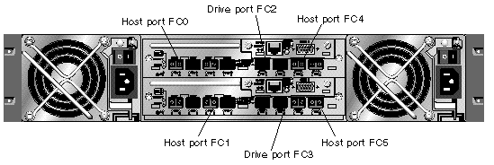
In a single-controller Sun StorEdge 3510 FC array, SFPs are usually plugged into FC0, FC1, FC4, and FC5. No SFPs are plugged into the drive channels. This configuration is appropriate for connecting to up to four hosts or fibre switches, with no connection to expansion units.

In a single-controller Sun StorEdge 3511 SATA array, SFPs are usually plugged into the left-most port of FC0, the left-most port of FC1, port FC4, and port FC5. No SFPs are plugged into the drive channels. This configuration is appropriate for connecting to up to four hosts or fibre switches, with no connection to expansion units.

7. Insert additional SFPs into the new I/O controller module as needed.
8. Install an I/O controller module into the top slot with the following steps.
a. Gently slide the I/O controller module into the unit until it clicks and is seated in the backplane.

|
Caution - Be sure that the module is properly inserted in the guide rails of the array. |
b. Turn the thumbscrews on the left and right sides of the I/O controller module clockwise until they are finger-tight to secure the module and to make the module's front panel flush with the chassis.
|
Note - To ensure that a thumbscrew is finger-tight, tighten it with a screwdriver and then loosen the thumbscrew counterclockwise a quarter turn. |
9. Repeat Step 4 and Step 5 to remove the I/O module in the lower slot and repeat Step 6 through Step 8 to install a second I/O controller module if you want to create a dual-controller RAID array.
11. Print or locate the Sun StorEdge 3000 Family Installation, Operation, and Service Manual for the Sun StorEdge 3510 FC and the Sun StorEdge 3511 SATA arrays to use for the remainder of this procedure.
12. Connect the new RAID array to a terminal emulation program or workstation through its serial port.
For information on how to connect to the serial port, refer to section 4.7, Configuring a COM Port to Connect to a RAID Array, in the installation manual.
On a Solaris system, use the tip command to access the array locally.
where n is the COM port identifier. For instance, if you have connected the array to the COM port identified as ttyb, use this command:
Refresh your screen by holding down the Control key on your keyboard and pressing the letter L key on your keyboard.
13. Set up an IP address for the chassis.
Refer to section 4.8, Setting an IP Address, in the installation manual.
|
Note - You can access the firmware application program directly through the serial port, or over Ethernet after you have set up the IP address. |
To connect by telnet to the chassis and access the firmware application, refer to section 4.9, Setting Up Out-of-Band Management Over Ethernet, in the installation manual.
14. Set the Controller Unique Identifier for each I/O controller module to 0 so that it adopts the chassis serial number with the Reset controller command.
The Controller Unique Identifier is used to create Ethernet MAC addresses and worldwide names. Perform the following steps to ensure that the Controller Unique Identifier is set to zero.
a. From the RAID firmware Main Menu, choose "view and edit Configuration parameters  Controller Parameters
  Controller Unique Identifier <hex>."
b. Type in the value 0 (to automatically read the chassis serial number from the midplane) and press Return.
The value 0 is immediately replaced with the hex value of the chassis serial number.
c. To implement the revised parameter value, on the RAID firmware Main Menu, choose "system Functions  Reset Controller." Confirm Yes when prompted.
15. On the RAID firmware Main Menu, choose "view system Information," and record the serial number of the array. You will use this number later.
16. For cabling and configuration instructions, refer to the Sun StorEdge 3000 Family Installation, Operation, and Service Manual for your array.
The new RAID array requires new cabling and first-time configuration.
Each operating system has additional procedures or requirements for seeing a new device. For instructions related to each operating system, refer to the appropriate appendix in the Sun StorEdge 3000 Family Installation, Operation, and Service Manual for your array.
17. After you create RAID logical drives on the new RAID array, restore the data onto the drives.
If you plan to use Sun StorEdge Configuration Service to manage and monitor the RAID array, perform the following additional steps.
|
Note - For first time configuration of a new RAID array, refer to the Sun StorEdge 3000 Family RAID Firmware User's Guide. |
1. Restart the Sun StorEdge Configuration Service agent and the console.
2. From the Sun StorEdge Configuration Service main window in the console, click View  Agent Options Management, and uncheck the box labeled Enable JBOD support.
You must disable the JBOD support temporarily in order to remove the old JBOD drive assignments.
4. Double-click on the server which had the JBOD array connected to it. Click the Probe button.
The JBOD connections are removed now.
5. Click Array Administration  Controller Assignment.
The Assign Server to Manage a RAID Controller window is displayed.
6. Check that the RAID array serial number recorded in Step 15 is displayed.
If the serial number is not displayed, check the operating system information in the Sun StorEdge 3000 Family Installation, Operation, and Service Manual for your array and your operating system documentation to complete the configuration. You will need to stop and restart the Sun StorEdge Configuration Service agent and console to see the revised configuration.
7. Select a server from the "Server to manage this controller" list and click Apply.
This enables the selected server to manage an array controller. It also disables all other servers listed from managing the same array.
8. To provide monitoring of other JBODs, click View  Agent Options Management, and check the box labeled Enable JBOD support.
Your initial configuration of the RAID array is now complete. Refer to the Sun StorEdge Configuration Service User's Guide for additional information.
If you are creating a dual-controller RAID array, perform the following steps with the firmware application, to ensure compatibility.
|
Note - For first time configuration of a new RAID array, refer to the Sun StorEdge 3000 Family RAID Firmware User's Guide. |
1. To check the controller firmware version of each module:
a. Remove one I/O controller module so that only one I/O controller module remains in the array.
b. Maintain a serial port connection to a terminal or workstation as described in Step 12.
c. In the firmware application, choose "view system Information" and record the Firmware Version.
d. Insert the second I/O controller module, remove the first module, and choose "view system Information" to record the Firmware Version of the second module.
e. To check that you have the latest firmware, go to:
and select Patch Portal. Browse in the Sun Alert Patch Report, or check the release notes for your array for firmware patch information.
2. Check the number on each I/O controller module faceplate where there is a four-digit number such as 03/50 or 04/50.
Both I/O controller modules must have the same first two digits which represent a SES/PLD firmware level in the module. If the two modules have two different numbers, for example 03 and 04, you must upgrade one I/O controller module to the higher level or both modules to the latest SES/PLD level. For more information, see Section 6.3.4, SES Firmware Update Sometimes Required with I/O Controller Module Replacements.
3. If the firmware versions of the two I/O controller modules do not match, download the latest firmware to each I/O controller module to ensure that they have the latest firmware and the same firmware.
To download new versions of controller firmware, disk drive firmware, or SES/PLD firmware, use one of the following tools and check the release notes for your array, or Sun Solve for the latest firmware patch:
This procedure replaces a defective FC or SATA switch module with a new switch module.
The following parts are included in the ID switch module replacement kit:
The following tool is required to complete this procedure:
1. Power off both RAID controllers.
2. If attached, unlock the front bezel cover with the provided key.
3. Grasp the front bezel cover on both sides and pull it forward and then down.
4. Press the right bezel arm (hinge) toward the left side to release it from the chassis hole.
The left bezel arm also disengages.
5. Note the location of the chassis bezel holes on each ear.
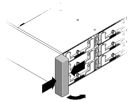
6. Remove the plastic cap from the left ear of the array.
a. Squeeze both sides of the cap at the top and the bottom.
b. Turn the cap toward the center of the array until it disengages and pull it free.
Be sure to follow Section 1.2, Static Electricity Precautions.
1. Record the ID switch setting on the switch module currently attached to the chassis.
You must set the same switch setting on the new switch module before you install it.
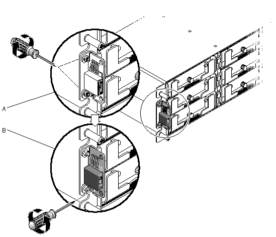
2. Remove the one panhead screw (B in FIGURE 9-10) attaching the switch module to the chassis.
|
Note - If the lower bracket screw obstructs the ID switch module screw (B in FIGURE 9-10), the chassis will have to be removed from the rack (if it is a rackmounted array) or the case (if it is a tabletop array) to gain access to the bracket screws (A in FIGURE 9-10) and remove them. Two #4-40 x 1/4-inch flathead screws are provided to replace the bracket screws, should they become damaged when removed. For details on removing the cover from a tabletop array, see Section 2.4.2, Converting a Tabletop Array to a Rack-Ready Array. |
3. Carefully pull the switch module out a short distance from the chassis.
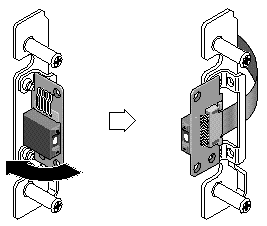
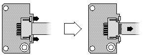
4. Detach the switch module from the ribbon cable by pulling out the tiny cable lock drawer and sliding the switch module free.
1. Before installing the new switch module, set the ID switch on the new module to the same switch setting recorded in Step 1 in Section 9.5.3, Removing the ID Switch Module.

|
Caution - Be sure that the ID switch has the correct setting. If it does not have the correct setting, the configuration might be invalid. |
2. Pull out the cable lock drawer on the new switch module.
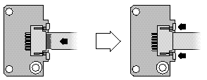
3. Insert the ribbon cable into the cable lock drawer and close the cable lock drawer to reconnect the cable to the switch module.
|
Note - The blue side of the ribbon cable must face towards the switch module and the ribbon contact area must be completely inserted into the switch module before the lock drawer is closed. |
4. Insert the panhead screw through the switch module and reattach the module to the chassis.
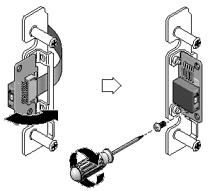
5. If the flathead screws (A in FIGURE 9-10) were removed, reattach these screws through the chassis flange into the bracket.
Replacement screws are provided in the ship kit in case the original screws were damaged during removal.
6. If it was removed in Step 2 in Section 6.6.3, restore the chassis to its case or rack.
7. Confirm that the switch setting is still the same value as that recorded in Step 1 in Section 9.5.3, Removing the ID Switch Module.
1. Push the top and bottom of the ear cap onto the ear, pressing in on the top side toward the center of the array until the ear cap snaps into place.
2. Insert the bezel arms into the chassis holes.
3. Lift the bezel into position and press it onto the front of the chassis until it is flush with the front.
4. Lock the bezel in the closed position with the keys.
5. Remove the keys if they were not initially inserted into the chassis.
6. Power on both power supply modules.
Copyright © 2007, Dot Hill Systems Corporation. All rights reserved.