| C H A P T E R 10 |
|
SCSI Module FRUs |
This chapter provides instructions for removing and installing field-replaceable units (FRUs) in Sun StorEdge 3310 SCSI arrays and Sun StorEdge 3320 SCSI arrays.
Topics covered in this chapter are:
|
Note - Be sure to follow Section 1.2, Static Electricity Precautions for all procedures. |
Be sure to follow Section 1.2, Static Electricity Precautions.
Prior to installing the I/O module, check to see if there is a 1/4-inch thin gasket on the top inside edge of the I/O module slot on the chassis.
If the gasket is on that edge, do not use the gasket provided with the I/O module FRU.
If there is no gasket on the top inside edge of the I/O module slot, install the enclosed gasket as follows:
1. Remove the plastic white backing on the back of the gasket.
2. Attach the adhesive side of the gasket to the top inside edge of the I/O module faceplate. This will look identical to the gasket already on the bottom inside edge of the I/O module faceplate.

|
Caution - Connected hosts must be inactive during this replacement procedure. |
1. Write down the cabling configuration for the SCSI I/O module and expansion unit connections so that you can reconnect the cables correctly with the new SCSI I/O module.
2. Power off both power supply modules on the array.
3. Remove all cables from the SCSI I/O module.
4. Write down the bus configuration (split-bus or single-bus configuration).
5. Ensure that all SCSI cables attached to the I/O module are labeled clearly, then remove all SCSI cables attached to the I/O module.
6. Turn the thumbscrews on the left and right sides of an I/O module counterclockwise until the thumbscrews are disengaged from the chassis.
7. Hold the thumbscrews, and using a slight downward pressure, pull evenly on the screws to disengage the I/O module.
1. With the power still off, slide the I/O module into the chassis far enough to engage the thumbscrews.

|
Caution - Be sure that the I/O module is properly inserted into the guide rails. |
2. Turn the thumbscrews on the left and right sides of the I/O module clockwise as tight as possible without using a screwdriver. Then push firmly with a single firm, two-handed push which should move the module about 1 cm.
3. Tighten the thumbscrews again. Then push firmly again with a single firm, two-handed push. Tighten the thumbscrews again until finger-tight.
|
Note - An improperly seated I/O module commonly causes SCSI channel errors. |
4. Reinstall all SCSI cables in their original positions.

|
Caution - You must connect the hosts to the correct host channels on the SCSI I/O module or your configuration will not work correctly. |
5. Power on both power supply modules.
Be sure to follow Section 1.2, Static Electricity Precautions.
1. Power off both power supply modules on the array.
Although the terminator module is technically hot-swappable, most users power off the array because the procedure requires that you will be removing and reinserting three modules during the procedure.

|
Caution - Connected hosts must be inactive during this replacement procedure. |
2. Remove all serial and Ethernet cables connected to the controller modules.
3. Remove both controller modules:
a. Turn the thumbscrews on the left and right sides of each controller module counterclockwise until the thumbscrews are disengaged from the chassis.
b. Hold the thumbscrews and pull out the controller module.
4. Hold the terminator module by the front edges, and pull it out of the chassis.
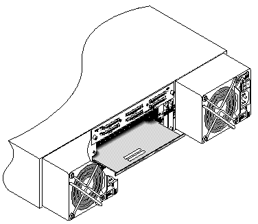
1. Keep the array powered off.
2. Slide the terminator module into the chassis until it is seated in the backplane.

|
Caution - Be sure that the terminator module is properly inserted into the guide rails of the array. |
3. Reinstall both controller modules:
a. Gently slide each controller module into the unit until the module is seated in the backplane.
b. Turn the thumbscrews on the left and right side of the controller module clockwise until they are finger-tight, to secure the module.
|
Note - To ensure that a thumbscrew is finger-tight, tighten it with a screwdriver and then loosen the thumbscrew counterclockwise a quarter turn. |
4. Reinstall the serial and Ethernet cables in their original positions.
5. Power on both power supply modules of the array.
Be sure to follow Section 1.2, Static Electricity Precautions. The Event Monitoring Unit (EMU) module is hot-swappable and can be replaced with the array powered on.
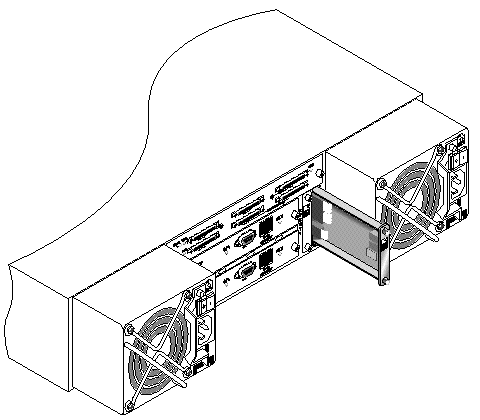
1. With the power on, and turn the thumbscrews on the top and bottom of an EMU module counterclockwise until the thumbscrews are disengaged from the chassis.
2. Hold the thumbscrews, and pull out the EMU module.
1. With the power on, slide the new EMU module into the chassis until it is firmly seated in the backplane and the module's front panel is flush with the chassis.

|
Caution - Be sure that the EMU module is properly inserted into the guide rails of the array. |
2. Turn the thumbscrews on the top and bottom of the EMU module clockwise until they are finger-tight, to secure the module.
|
Note - To ensure that a thumbscrew is finger-tight, tighten it with a screwdriver and then loosen the thumbscrew counterclockwise a quarter turn. |
The Sun StorEdge 3310 SCSI array and the Sun StorEdge 3320 SCSI array box FRU includes a chassis, its drive midplane, and its backplane. This product is ordered to replace a box that has been damaged or whose midplane or backplane has been damaged.
To make a fully functional array, you must add the following parts from the replaced array:
To install the individual modules, use the replacement instructions provided in this guide.
To configure the array, refer to the installation manual for your array, located on your Sun StorEdge 3000 Family Documentation CD.
To replace the chassis frame of an existing RAID array or expansion unit, perform the following steps.
1. Connect to the firmware application via the serial interface (tip for Solaris/Linux) or via telnet.

|
Caution - Connected hosts must be inactive during this replacement procedure. |
2. If the defective array is a RAID array:
From the RAID firmware Main Menu, choose "view and edit Configuration parameters  Controller Parameters."
Write down the Controller Unique Identifier (hex) - value.
3. Power off both power supply modules on the defective array.
4. Ensure all SCSI cables attached to the I/O module are labeled clearly.
5. Write down the defective array's cabling configuration.
6. Remove all SCSI cables attached to the I/O module.
7. If the defective array is a RAID array, remove all serial and Ethernet cables connected to the RAID controllers.
8. Label each disk drive with its disk slot position in the array.
9. Remove the RAID controllers (if applicable), terminator board (if applicable), I/O modules, EMUs, power supply modules, and disk drives from the defective array.
10. Remove the defective chassis.
11. Obtain the replacement chassis.
12. Re-install all previously removed modules in their original positions in the replacement array.
13. Reinstall all SCSI, serial, Ethernet, and power cables in their original positions.
14. Power on both power supply modules on the replacement array.
15. If the replacement array is an expansion unit or JBOD, refer to your installation manual to configure it.
16. If the replacement chassis is a RAID array, proceed with the following steps:
a. Connect to the array console menu interface via the serial interface (tip for Solaris/Linux) or via telnet.
b. From the RAID firmware Main Menu, choose "view and edit Configuration parameters  Controller Parameters
  Controller Unique Identifier (hex)."
17. If this array is being used by clustered hosts, or for any other reason its attached hosts require that their Device IDs remaining consistent, perform these steps:
a. Set Controller Unique Identifier (hex) to the value you wrote down in Step 2.
b. Reset the RAID Controllers: From the RAID firmware Main Menu, choose "system Functions  Reset controller." Confirm Yes when prompted.
c. Proceed with Step 19.
18. If this array is NOT being used by clustered hosts, perform these steps:
a. On the RAID firmware Main Menu, choose "view and edit Configuration parameters  Controller Parameters
  Controller Unique Identifier <hex>."
b. Type in the value 0 (to automatically read the chassis serial number from the midplane).
The value 0 is immediately replaced with the hex value of the chassis serial number.
c. To implement the revised parameter value, choose "system Functions  Reset Controller." Confirm Yes when prompted.
19. Connect the array to hosts according to the configuration identified in Step 4 and Step 5.
The chassis replacement is now complete.
The external terminator is necessary only during certain maintenance tasks performed with a Sun StorEdge 3310 SCSI JBOD or a Sun StorEdge 3320 SCSI JBOD split-bus configuration, which is connected directly to multiple servers in a clustering environment (most often, the Sun Cluster environment). With many maintenance tasks, you remove a failed or outdated part and replace it immediately; this is standard procedure.
However, if you have an unusual situation and need to remove a host connection from the JBOD for a prolonged period, you might need to preserve the other host connections and activity on the JBOD.
The Sun SCSI LVD/MSE external terminator is part number XTA-3310-SC-TERM (595-6750-01).
If you have JBOD I/O modules, part number 370-5396-02/50 or higher, use this information.
|
Note - This new I/O module supports both single-initiator and multi-initiator split-bus configurations. The older I/O module supports only single-initiator split-bus configurations. |
If you have earlier I/O modules and do not have JBOD I/O modules, part number 370-5396-02/50 or higher, see Section 10.5.2, Older JBOD Split-Bus Configurations.
To preserve all original SCSI IDs and correct termination on a split-bus JBOD in a cluster environment, insert an external terminator in all cases where a SCSI port becomes empty that was not empty in the original configuration. This maintains the SCSI drive IDs for the active host connections. For an example of two removed cables and two inserted terminators, see FIGURE 10-3.
In a split-bus configuration, the SCSI IDs change according to the termination on the SCSI ports. If your original configuration has both SCSI ports connected on a bus connected to hosts, the SCSI IDs are 0 to 5. If only the bottom port is connected to a host, the SCSI drive IDs are 8 to 13.
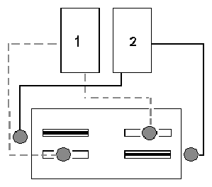
To keep other host connections operational while one host connection is temporarily removed, perform the following steps.
1. Stop all host I/O activity on the host bus where the removal of a cable will occur.
2. Disconnect the array from the host SCSI cable of the server that requires the maintenance work from the array.
3. Insert the external terminator into the empty SCSI port on the array.
The external terminator preserves the original SCSI IDs.
4. Resume host I/O activity on the remaining hosts.
If you have earlier I/O modules and do not have JBOD I/O modules part number 370-5396-02/50 or higher, use the information in this section.
|
Note - The older I/O modules only supported single-initiator split-bus configurations. |
In a split-bus configuration, the SCSI IDs change according to the termination on the SCSI ports. If your original configuration has both SCSI ports connected on a bus connected to hosts, the SCSI IDs are 0 to 5. If only the bottom port is connected to a host, the SCSI IDs are 8 to 15. To preserve all original SCSI IDs and correct termination on a split-bus JBOD in a cluster environment, insert an external terminator in all cases where a top SCSI port is empty but was not empty in the original configuration.
To keep other host connections operational while one host connection is temporarily removed, perform the following steps.
1. Stop all host I/O activity on the host bus where the removal of a cable will occur.
2. Disconnect the array from the host SCSI cable of the server that requires the maintenance work from the array.
3. In a split-bus configuration, if two hosts are connected to one bus, and the host cable to the bottom port of the array is disconnected, move the cable of the top port to the bottom port.
The moved cable provides termination to the bottom port.
4. Insert the external terminator into the empty top SCSI port on the array.
The external terminator preserves the original SCSI IDs, which are 0 to 5 on each bus that has two host connections established.
5. Resume host I/O activity on the remaining hosts.
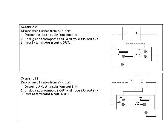
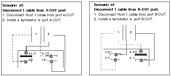
You can have situations in which one or two SCSI cables are temporarily removed from a standard SCSI array configuration.
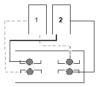
In each of the four scenarios in FIGURE 10-5 and FIGURE 10-6, a single cable was removed from the original configuration shown in FIGURE 10-4. In each of these scenarios, one external terminator was required.
|
Note - The bottom input ports support only host SCSI connections and do not support external terminators. |
The filler panel FRU is a single metal panel used to cover an empty controller module slot on the rear of a Sun StorEdge 3310 SCSI array or a Sun StorEdge 3320 SCSI array. Most often, this occurs when you want to remove a controller module and change a dual-controller array to a single-controller array. The filler panel protects the interior of the array.
To install a filler panel, perform the following steps.
1. Remove the controller module according to Section 7.3.1, Removing a SCSI Controller Module.
2. Position the filler panel so that it covers the empty slot and the thumbscrews overlay the thumbscrew holes.
3. Turn the thumbscrews on the left and right sides of the filler panel clockwise until the thumbscrews are finger-tight, to secure the panel on the array.
Copyright © 2007, Dot Hill Systems Corporation. All rights reserved.