|
|
This document
contains important release information about the Sun StorageTek 2500
Series Arrays and information that was not available at the time the
product documentation was published. These release notes cover the Sun
StorageTek 2500 Series Array, Release 1.3 and 06.70.42.10 firmware, and
related hardware issues. Read this document so that you are aware of
issues or requirements that can affect the installation and operation
of the Sun StorageTek 2500 Arrays.
A firmware patch for the Sun StorageTek Common Array Manager Software, Release 6.0.1, adds support for a third expansion tray and 48 drives. Refer to Installing the 6.70.54.10 Patch for 48 Drive Support.
For information on management software requirements, operations, and issues, see the Sun StorageTek Common Array Manager Software Release Notes, Release 6.0.1.
The release notes consist of the following sections:
This section describes the main features of the Sun StorageTek 2500 Array 1.3 release, including the following:
The Sun StorageTek 2540 Array, the Sun StorageTek 2530 Array, the Sun StorageTek 2510 Array, the Sun StorageTek 2501 Expansion Module, are a family of storage products.
The Sun StorageTek 2500 Arrays contains disk drives for storing data and controllers that provide the interface between a data host and the disk drives. The Sun StorageTek 2540 Array provides a Fibre Channel connection from the data host to the controller. The Sun StorageTek 2530 Array provides a Serial Attached SCSI (SAS) connection from the data host to the controller. The new Sun StorageTek 2510 Array supports Internet Small Computer Systems Interface (iSCSI) over Ethernet networks.
The Sun StorageTek 2501 Expansion Module provides additional storage. You can attach the drive expansion tray to the Sun StorageTek 2540, 2530, and 2510 Arrays.
Release 1.3 supports iSCSI on the Sun StorageTek 2510 Array. iSCSI uses the Small Computer Systems Interface (SCSI) protocol over Ethernet networks to communicate between client initiators and target storage devices.
Consult the Sun StorageTek 2500 Series Array Hardware Installation Guide for initial information about configuring iSCSI and the online help in the management software for additional information and procedures.
Auto Service Request (ASR) is a feature of the array management software that monitors the array system health and performance and automatically notifies the Sun Technical Support Center when critical events occur. Critical alarms generate an automatic Service Request case. The notifications enable Sun Service to respond faster and more accurately to critical on-site issues.
You enable the Auto Service Request capability by using the Sun StorageTek Common Array Manager software to register devices to participate in the ASR service. Refer to the Sun StorageTek Common Array Manager Release Notes, Release 6.0.1 or higher, for more information.
Premium features require licenses which must be ordered separately. The following premium features are available for 2500 Series Arrays:
| Note - The 2500 Series Arrays provide two free storage domains. Storage domain licenses are required to map additional initiators on data hosts to volumes. |
The Sun StorageTek 2500 Series Array controller and expansion trays are shipped separately. The AC power cords are ordered separately. The following is a list of the contents in the tray ship kits. There may also be Read Me first notices.
Content for the 2540 controller tray only:
Ship kit for each 2501 expansion tray:
| Note - .5 meter SAS cables are being replaced with 1 meter SAS cables. The .5 meter cable will ship for a period of time. The 1 meter SAS cable can be ordered separately. |
The Sun StorageTek Common Array Manager software (6.0.1 and above) provides an easy-to-use interface from which you configure, manage, and monitor Sun StorageTek storage systems, including the Sun StorageTek 2500 Series Array. You can also use the Common Array Manager software to diagnose problems, view events, and monitor the health of your array. Each release of the Common Array Manager provides the latest firmware updates for all the arrays it supports and provides the means to upload the firmware to them.
The Common Array Manager is the only supported management software for the 2500 Series Array. Refer to the Release Notes and other Sun StorageTek Common Array Manager documentation described in Release Documentation.”
The software and hardware products that have been tested and qualified to work with the Sun StorageTek 2500 Series Array are described in the following sections:
The following table describes 2500 Series array controller firmware versions, how they were delivered and their pre-requisites.
|
For 2540 and 2530 arrays, the 06.70.00.11 patch must be installed first. |
||
|
CAM 6.0.1 must be installed. Refer to Installing the 6.70.54.10 Patch for 48 Drive Support for instructions. You can install the 06.70.54.10 firmware from 06.70.00.11 or 06.70.42.10. |
The following section lists the firmware baseline files to work with this 2500 Series Array Release 1.3 and delivered with the Sun StorageTek Common Array Manager software, Release 6.0.1.
For the latest patches available for your system, check SunSolve at: http://www.sunsolve.sun.com.
In the following tables, the file path listed in the Firmware File column (for example, nge/RC_0670xxxx_desperado.dlp) is the relative path to the /images subdirectory where the firmware files are located.
TABLE 2 lists the controller information for the Sun StorageTek 2500 arrays.
TABLE 3 lists the NVSRAM information for the Sun StorageTek 2500 arrays.
TABLE 4 lists the IOM information for the 2500 Series Arrays
TABLE 5 lists the size, speed, and tray capacity for the supported disk drives in the Sun StorageTek 2500 Series Array.
This section provides the data host requirements of the 2500 Series Array at the time this document was produced. These requirements can change; for complete up-to-date compatibility requirements, contact your Sun sales or support representative.
Data host requirements for 2540 arrays, which support Fibre Channel connections to the data host, are different from 2530 arrays, which use SAS connections to the data host, and the 2510 array, which uses Ethernet connections.
For supported HBAs and switches, refer to:
https://extranet.stortek.com/interop/interop
The 2540 Array supports Fibre Channel-only connections to the data host. The information in this section applies only to data hosts with Fibre Channel connections.
TABLE 6 lists the supported host Operating Systems (OSs) and multipathing availability. HBAs must be ordered separately, from Sun or their respective manufacturers. Sun HBAs can be ordered from the following site: http://www.sun.com/storagetek/networking.jsp
You can download HBA drivers and other host software from the Sun Downloads, http://www.sun.com/download/index.jsp. Download operating system updates from the web site of the operating system company.
The data hosts require software for multipath or single path support. Follow the instructions in the Sun StorageTek 2500 Series Array Hardware Installation Guide to download and install the software from the Sun Download Center.
Solaris patches can be downloaded from: http://www.sun.com/software/download/
http://sunsolve.sun.com/show.do?target=patchpage
TABLE 7 lists the required patches for Solaris data hosts.
The 2530 Array supports SAS-only connections to data hosts. The information in this section applies only to data hosts with SAS connections.
TABLE 8 lists supported 2530 data host platforms and indicates the kind of support they have for SAS connections.
|
Included in OS with patch 125081-10. See TABLE 9. |
|||
|
Included in OS with patch 125081-10. See TABLE 9. |
|||
* 12111-07 is a pre-requisite patch and must be installed prior to 125081-14 only if a system administrator wishes to have a per-HBA mpxio-disable setting for an UltraSPARC host where the SAS HBA is connected with the PCI-e interface.
This issue does not occur if there is no per-hba mpxio-disable setting. This issue does not occur on PCI-X attached SAS HBAS. This issue does not occur on x86/x64 hosts.
The 2510 Array supports iSCSI with Ethernet connections to Network Interface Cards (NICs) on the data host.
TABLE 10 lists the supported host Operating Systems (OSs) and multipathing availability. You can download host software from the Sun Downloads, http://www.sun.com/download/index.jsp. Download operating system updates from the web site of the operating system company.
TABLE 11 lists the required patches for 2510 Solaris data hosts.
This section describes release-specific steps for installing the firmware baseline for this release.
| Note
- For 2540 or 2530 arrays
only. You can install the 06.70.42.10 firmware baseline only if your
array already runs the 06.70.00.11 firmware which is included in Installing the
06.70.00.11 Firmware Patch. The patches are based on the installed
version of Sun StorageTek Common Array Manager software: 5.1.3 or 6.0.
If you need to install the patch, perform the off-line upgrade in Installing the
06.70.00.11 Firmware Patch before installing the Release 1.3
firmware baseline.
ST 2510 arrays do not need this patch. For ST 2510 arrays, proceed to Installing Release 6.0.1 Firmware Baseline. |
This release requires that you have 06.70.00.11 firmware installed before upgrading to the baseline firmware. The 06.70.00.11 firmware was delivered with firmware patches based on the installed version of Sun StorageTek Common Array Manager software: 5.1.3 or 6.0.0 You must have one of the patches installed before proceeding with the Release 1.3 (CAM v6.0.1) firmware baseline installation.
The patches are available from the Sun Download Center: http://www.sun.com/software/download/
http://sunsolve.sun.com/show.do?target=patchpage
|
1. Download the patch listed in Required 06.70.00.11 Firmware Patches from the Sun download center.
2. Stop all IO from all of the connected data hosts.
3. Unmount any file systems associated with the volumes on the array.
Use system administration commands for your operating system CLI to unmount the volumes.
4. Login to the management host as root.
5. Follow the instructions in the README in the patch to:
a. Download or copy the patch to the software installation directory
b. Untar and/or unzip the patch
6. Use Sun StorageTek Common Array Manager software to upgrade the firmware.
a. On the Java Web Console page, click Sun StorageTek Common Array Manager.
b. Go to the Storage System Summary page and select the arrays to be upgraded.
c. Click the Upgrade Firmware button.
7. When the management software indicates that the firmware upgrade is complete, restart each array controller one at a time.
a. Turn on the power switch on the controller.
8. When the controllers are back online, use the management software to verify that the volumes are assigned to the active controller.
The Volume Details page allows you to select the owning controller.
9. For switches that use WWPN zoning, updating firmware in this patch will update the existing WWPNs. You will need to correct all zoning to match these new WWPNs.
10. Restart the I/O from the data hosts.
11. Remount any file systems associated with the volumes on the array.
Use system administration commands in your Operating System CLI to mount the volumes.
Once you have installed the required patch noted in the last section, you can use the Common Array Manager software to install the current 6.70.42.10 firmware baseline required for this release. The Common Array Manager software and baseline firmware is included on the Sun StorageTek 2500 Series Array CD, or in the package you obtain from the Sun Download Center: http://www.sun.com/software/download.
|
1. Install the current management software and register the array, as described in Sun StorageTek Common Array Manager Software Installation Guide, Release 6.0.1 or higher.
2. Install the firmware baseline on the array using the Common Array Manager interface.
You can upgrade the firmware on the 2540 Array without stopping I/O. For firmware for expansion modules, disk drives, and IOMs, it is recommended that a maintenance period of low activity be scheduled in order to execute the upgrade process.
a. On the Java Web Console page, click Sun StorageTek Common Array Manager.
b. Go to the Storage System Summary page and select the arrays to be upgraded.
c. Click the Install Firmware Baseline button.
d. Follow the prompts to install the baseline.
After you install the Sun StorageTek Common Array Manager software, v6.0.1, you can apply the 06.70.54.10 patch. That patch adds support for a third expansion tray and 48 drives. The patch numbers are:
The patches are available from the Sun Download Center: http://www.sun.com/software/download/
http://sunsolve.sun.com/show.do?target=patchpage
The following sections provide information about known issues and bugs filed against this product release:
If a recommended workaround is available for a bug, it follows the bug description.
The ST 2510 array is not currently NEBS Level 3 compliant. It will become compliant approximately 8 weeks post-RR. Customers relying on this NEBS certification should check with their Sun representatives before acquiring this array for NEBS-specific applications to verify that the ST 2510 is certified.
Bug 6615356 - SYMbol task ServsymRpcHandle periodically dies, causing the management software to lose communication with the array.
The cause has been identified and will be corrected in future releases.
Workaround - Rebooting the array corrects the problem.
Bug 6611655 - Negative counter values display for iSCSI Statistics large counter values. The values should be unsigned.
Workaround - Resetting the baseline under Administration->Performance in the management software resets the values.
Bug 6624755 - For iSCSI on the 2510 Array only, creating an initiator with the same name as a host returns error message 57: “The operation cannot complete because the identifier or name you provided already exists. Please provide another identifier or name and then retry the operation.”
Workaround - Do not create an initiator with the same name as a host.
Bug 6620100 - For the 2510 Array, the Controller Summary page of the management software shows the Host Board Type as UNKNOWN. For example:
public static final int HB_TYPE_UNKNOWN 1
Workaround - Keep a manual record of iSCSI host boards.
Bug 6651908 - IPv6 performance statistics display on the iSCSI Performance - Ethernet - TCP/IP page in the management software. They should not.
Workaround - Ignore the IPv6 performance statistics on this page.
Bug 6560293 and 6650124- The SAS port link status in the management software may be incorrect.
Bug 6522947 - Removing a SAS controller results in outdated information on the Controller Details page in the management software. The status correctly reports the controller as removed. Replacing the controller corrects the state.
Bug 6522938 - For SAS, using the CLI to create a new volume on an array with high data input and output returns in a timeout and an error code of 4.
Workaround - Verify if the new volume was created and if not try the operation when there is less I/O traffic.
This section describes general issues related to the Sun StorageTek 2500 Series Array hardware and firmware.
Bug 6527155 - Do not use World Wide Port Names as names for initiators. Doing so will result in serious problems in array operations. The Common Array Manager software will prevent you from doing this.
Bug 6587720- The Array Service Required LED will light after powering down a data host, connecting FC cables between the HBA and controllers, and powering up the host server.
This is working as designed. Under a Direct Connect environment, rebooting the connected data host will cause a FC link down alarm. This is an expected alarm and the Amber Service Required LED is expected to illuminate. As soon as the link is back up, the Alarm should clear and the LED should turn off. The same behavior would be expected if a cable were unplugged form the HBA, or if there was a error with the HBA port or the HBA itself.
Under a switch environment, this will not occur unless a cable is unplugged from the switch, the switch is rebooted, or is having errors. Rebooting the host will not cause the link to go down because the link from the controller SFP to the switch will remain 'up'.
Bug 6541881 - A cable pull returned to the wrong HBA port can cause a panic. The cause is known and a fix is being worked on.
Workaround - Try to ensure that you plug the cable back into the port it was originally in if your system is running. If you need to move the cable to a different port, try to do so when the system is not online.
Bug 6529172 - A snapshot volume that is disabled can be automatically re-enabled after a firmware update occurs. If the snapshot volume is full, it can start generating warning events.
Workaround - Disable the snapshot again after the firmware update.
Bug 6550702 and 6547615 - If you migrate an expansion module with licensed storage domains into an array that has a different number of licenses, an alarm will be generated.
Workaround -For a mismatch of license numbers, disable the licenses on the expansion module. Then disable the storage domains on the expansion module. The array will return to the licenses for the array (which is compliant), and the alarm will clear. Add any new licenses, if needed.
Bug 6560279 - When a FC port is not connected to a Fabric or FC-AL topology, the Port Summary table reports the speed as 4Gbps. The port speed should read “Unknown” in the Summary page.
Bug 6581396 - The sscs list fru command displays Disk Type and Description as "All" and "All disk drive" respectively for a removed disk drive which was configured as a hotspare.
It should display "Unknown" as a drive type and "Unknown disk drive" in the Description field.
Bug 6509762 - After a firmware upgrade to an Input-Output Module (IOM), the array will display a Check Condition - Microcode Changed message on all hosts.
After a firmware upgrade, an automatic failback was generated. When the switch port connecting the data host was enabled, the auto failback failed, indicating that it did not process the MICROCODE_CHANGED message.
Workaround - There are two workarounds:
1) Perform a manual failover. The issue will not happen.
2) After updating the IOM firmware, manually forcing a failover and failback of all effected LUNs on any mapped Solaris host will clear out the condition.
Bug 6509331 - In Solaris, under heavy data traffic, host-initiated failover may generate error messages in /var/adm/messages even though the failover is successful.
Workaround - In the CLI, use the Solaris luxadm command to verify that the failover was successful.
$ luxadm di /dev/rdsk/c9t600A0B8000245D4C0000310A458A852Bd0s2
DEVICE PROPERTIES for disk: /dev/rdsk/c9t600A0B8000245D4C0000310A458A852Bd0s2
  Vendor:               SUN
  Product ID:           LCSM100_F
  Revision:             0617
  Serial Num:           1T60325953
  Unformatted capacity: 3072.000 MBytes
  Write Cache:          Enabled
  Read Cache:           Enabled
    Minimum prefetch:   0x3
    Maximum prefetch:   0x3
  Device Type:          Disk device
  Path(s):

  /dev/rdsk/c9t600A0B8000245D4C0000310A458A852Bd0s2
  /devices/scsi_vhci/ssd@g600a0b8000245d4c0000310a458a852b:c,raw
   Controller           /devices/ssm@0,0/pci@18,600000/SUNW,qlc@1/fp@0,0
    Device Address              202400a0b8245db7,5
    Host controller port WWN    210000e08b883b2e
    Class                       secondary
    State                       STANDBY
   Controller           /devices/ssm@0,0/pci@18,600000/SUNW,qlc@1,1/fp@0,0
    Device Address              202500a0b8245db7,5
    Host controller port WWN    210100e08ba83b2e
    Class                       primary
    State                       ONLINE
Note that the primary controller is online.
2. Issue the failover command.
An error message is generated indicating failure.
$ luxadm failover secondary /dev/rdsk/c9t600A0B8000245D4C0000310A458A852Bd0s2
 Error: Unable to perform failover, standby path unavailable
3. Verify the path characteristics.
$ luxadm di /dev/rdsk/c9t600A0B8000245D4C0000310A458A852Bd0s2
DEVICE PROPERTIES for disk: /dev/rdsk/c9t600A0B8000245D4C0000310A458A852Bd0s2
  Vendor:               SUN
  Product ID:           LCSM100_F
  Revision:             0617
  Serial Num:           1T60326060
  Unformatted capacity: 3072.000 MBytes
  Write Cache:          Enabled
  Read Cache:           Enabled
    Minimum prefetch:   0x3
    Maximum prefetch:   0x3
  Device Type:          Disk device
  Path(s):

  /dev/rdsk/c9t600A0B8000245D4C0000310A458A852Bd0s2
  /devices/scsi_vhci/ssd@g600a0b8000245d4c0000310a458a852b:c,raw
   Controller           /devices/ssm@0,0/pci@18,600000/SUNW,qlc@1/fp@0,0
    Device Address              202400a0b8245db7,5
    Host controller port WWN    210000e08b883b2e
    Class                       secondary
    State                       ONLINE
   Controller           /devices/ssm@0,0/pci@18,600000/SUNW,qlc@1,1/fp@0,0
    Device Address              202500a0b8245db7,5
    Host controller port WWN    210100e08ba83b2e
    Class                       primary
    State                       STANDBY
Note that the secondary controller is now online, indicating that the failover occurred.
Bug 6514411 - Inserting a disk drive into a tray by pushing on its housing until it is all the way in causes the drive to stop without being fully inserted and with the drive handle protruding.
Workaround - The correct way to insert a disk drive into the tray is as follows:
|
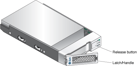
1. Push the release button next to the disk drive to release the latch handle.
FIGURE 1
Releasing the Latch Handle

|
Caution - Potential loss of data access - Data might be lost if an active disk drive is removed. If you remove an active disk drive accidentally, wait at least 30 seconds before reinserting it. |
2. Use the latch handle to slowly pull the failed disk drive out of the tray.

|
Caution - Use care when handling any disk drive. Make sure all ESD precautions are being followed. |
3. When the drive is removed push the latch handle in to protect the failed disk drive from damage.
4. Unpack the new disk drive and do one of the following:
5. Wait 30 seconds after the failed disk drive has been removed.
6. On the new disk drive, push the release button to release the latch handle.
7. Partially insert the drive into desired slot location. See FIGURE 2.

|
Caution - In some drive bays, full insertion at this point without controlling the motion of the lever may cause the lever to bind. |
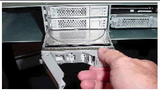
8. Grasp the lever and continue inserting the drive until you can easily rotate the lever toward the closed or latched position. See FIGURE 3.
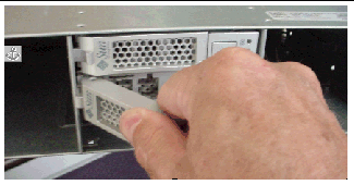
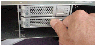
9. Press firmly on the lever until it latches and the drive is fully inserted. See FIGURE 4.
| Note - Pressing harder should not cause additional inward motion of the drive. |
The latch handle will click into place when the drive is fully inserted.
FIGURE 4 Fully Inserting the Drive.
10. After the disk drive is fully inserted, the green Ready/Active LED will flash and then remain on to indicate a ready state.
A flashing Ready/Active LED indicates that data is being restored to the new disk drive.
|
1. Access the Service Advisor software and verify that the State value is Enable and Status value is OK for the new disk drive
If the State and Status values are not Enable and OK, contact your Sun Service provider or your next level of technical support.
2. From the Service Advisor software, do the following:
Bug 6482519 - The luxadm probe command displays UTM LUNs on x86 platforms. The UTM (Management) LUN is a reserved space, normally hidden, where the specific configuration settings for your array are stored.
Bug 6502673 - A battery replaced in a controller reports a failed battery event, while it is recharging. After the battery is fully recharged, this alarm will go away.
Bug 6503171 - Battery event messages do not specify which of the two controllers the referenced battery is in.
For battery events, the array only reports the tray where it occurs, not the slot.
Workaround - For non-critical events, collect the support data and find the corresponding event in the MEL log. For critical events, the third amber LED lights on the front of the controller with the failed battery.
Bug 6514739 - If a bad SFP is inserted in the FC port of a 2540 array, there may not an indication in the fault list that it is bad.
Certain failure modes of an SFP may not be detected by the array firmware immediately upon insertion and the management software could report the link state as optimal.
However, when you initiate I/O on the channel with the damaged SFP, it will be reported as failed.
Workaround - Check the fault LED and link LED for link failure. Check the event log for a failure event at the time of the SFP insertion and when you initiate I/O.
Bug 6523608 - Refreshing a snapshot does not update the filesystem if there is insufficient reserve space, yet a message displays indicating success. The array’s event log says the resnap completed successfully.
Workaround - In the snapshot feature of the management software, configure snapshots to fail if sufficient reserve space is not available. The fail message will prompt you to increase the reserve space.
Bug 6523624 - If a firmware upgrade to an expansion module fails, the array may not clear the failed session automatically.
Workaround - After 20 minutes, retry the upgrade. If the upgrade fails again, power cycle the array to clear the failure.
A busy array can increase the management software’s response time.
Bug 6501029 - When the management software lists a disk as failed and the Service Advisor procedure for replacing drives is followed, the step to verify that the disk is ready to remove may not list the failed disk.
Workaround - Use an alternative menu option, Array Troubleshooting and Recovery, to view the status of the disk.
This section describes known issues and bugs related to the Sun StorageTek 2500 Series Array release documentation.
A patch is available for Release 6.0.1 that adds support for a third expansion tray and 48 drives. Cabling instructions for the third expansion tray has not yet been added to Sun StorageTek 2500 Series Array Hardware Installation Guide or Service Advisor.
The configuration naming convention is “controllers x trays” where the first number is the controller tray and the second is the sum of the controller tray and the number of expansion trays. For example, 1x1 is a standalone controller tray, 1x2 is the controller tray and one expansion tray, 1x3 is the controller tray and 2 expansion trays, 1x4 is the controller tray and 3 expansion trays (TABLE 13).
| Note - Do not add more expansion trays than the array supports. |
Use the following instructions to connect the dual-RAID controller tray to one or more expansion trays.
Keep the following points in mind when adding expansion trays to your storage array:
A Controller tray has two expansion ports, one on the Controller A module and one on the Controller B module. To connect an expansion tray, connect an SAS cable from each expansion port on the controller to each In port on the expansion tray. TABLE 14 shows a 1x2 array configuration consisting of one controller tray and one expansion tray. Two SAS cables are required.
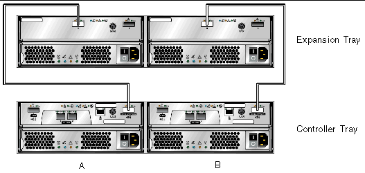
To cable a 1x2 array configuration:
1. Locate the Controller A and Controller B expansion ports at the back of the controller tray (TABLE 14).
2. Locate the In and Out expansion ports at the A-side and B-side back of the expansion tray (TABLE 14).
3. Connect one SAS cable between the Controller A expansion port and the A-side In port on the expansion tray (TABLE 14).
4. Connect one SAS cable between the Controller B expansion port and the B-side In port on the expansion tray (TABLE 14).
Each additional expansion tray is added to the preceding expansion tray by connecting SAS cables from the Out ports of the first tray to the In ports of the next tray. TABLE 15 illustrates a 1x3 array configuration consisting of one controller tray and two expansion trays. The cable connections on the B-side are reversed (the cable from the controller A expansion port goes to the In port of expansion tray 1; the cable from the controller B expansion port goes to the In port on expansion tray 2) for maximum redundancy. This pattern continues for each additional tray you add. Two more SAS cables are required for each additional tray.
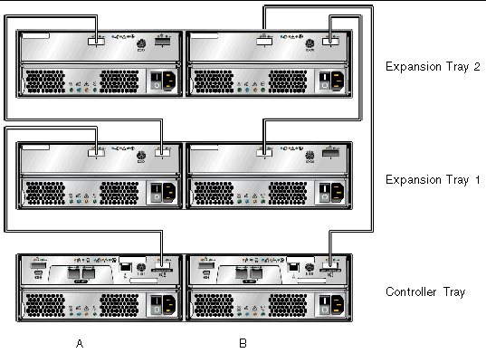
To cable a 1x3 array configuration for maximum redundancy:
1. Locate the Controller A and Controller B expansion ports at the back of the controller tray (TABLE 15).
2. Locate In and Out expansion ports at the A-side and B-side back of the expansion tray (TABLE 15).
3. Connect one SAS cable between the Controller A expansion port and the A-side expansion In port of expansion tray 1 (TABLE 15).
4. Connect one SAS cable between the Controller B expansion Out port and the B-side expansion In port of expansion tray 2 (TABLE 15).
5. Connect one SAS cable between the expansion tray 1 Out port and the A-side expansion In port of expansion tray 2 (TABLE 15).
6. Connect one SAS cable between the expansion tray 2 B-side Out port and the B-side In port of expansion tray 1 (TABLE 15).
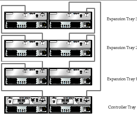
To cable a 1x4 array configuration for maximum redundancy:
1. Locate the Controller A and Controller B expansion ports at the back of the controller tray (TABLE 16).
2. Locate In and Out expansion ports at the A-side and B-side back of the expansion tray (TABLE 16).
3. Connect one SAS cable between the Controller A expansion port and the A-side expansion In port of expansion tray 1 (TABLE 16).
4. Connect one SAS cable between the Controller B expansion Out port and the B-side expansion In port of expansion tray 3 (TABLE 16).
5. Connect one SAS cable between the expansion tray 1 Out port and the A-side expansion In port of expansion tray 2 (TABLE 16).
6. Connect one SAS cable between the expansion tray 3 B-side Out port and the B-side In port of expansion tray 2 (TABLE 16).
7. Connect one SAS cable between the expansion tray 2 Out port and the A-side expansion In port of expansion tray 3 (TABLE 15).
8. Connect one SAS cable between the expansion tray 2 B-side Out port and the B-side In port of expansion tray 1 (TABLE 15).
The Sun StorageTek 2500 Series Array Hardware Installation Guide, part number 820-0015-10, lists Solaris 8 as supported for data hosts. Only Solaris 9 and/or 10 are supported, depending on the application.
Bug 6538943 - The Sun StorageTek 2500 Series Array Hardware Installation Guide, Part No. 820-0015-10, states in Chapter 2:
“Expansion trays must be added with the power to the array and I/O data transfer turned off.”
This is incorrect. It is best to add an expansion tray to a running array instead of one that is powered off. Limiting I/O traffic is recommended for the duration of the reconfiguration.
Step 6 on page 51 of Sun StorageTek 2500 Series Array Hardware Installation Guide states, “Connect one SAS cable between the expansion tray 2 B-side Out port and the B-side In port of expansion tray 2.” This is incorrect. You should connect the cable between the expansion tray 2 B-side Out port and the B-side In port of expansion tray 1.
Corresponding Figure 19 is correct.
The Sun StorageTek 2500 Array Hardware Installation Guide documents the default IP addresses (Configuring IP Address of the Array Controllers), but does not include the netmask. The netmask for the default addresses is 255.255.255.0.
Bug 6515249 - In Chapter 2 of the Sun StorageTek 2500 Array Hardware Installation Guide the list of tools needed for the array installation in a rack does not list a flathead screwdriver, which is required if you need to loosen the rail extension screws.
The service life of the battery pack is three years, at the end of which the battery pack must be replaced. The Sun StorageTek 2500 Array Hardware Installation Guide incorrectly lists the life as two years.
This section provides useful operational information not documented elsewhere.
In-band for Linux requires Linux Red Hat Enterprise v5.1.
When a drive fails, wait 60 seconds after removing the failed drive before you put in a new drive.
The 2500 Series array includes two storage domains. You must purchase a premium license to use additional storage domains.
Configure management objects while an import array job is running might interfere with the import. Be sure that everyone who uses the destination array does not configure any objects (including volumes, initiators, mappings, etc.) while the import is in progress.
When you create a volume and label it, you can start using the volume before it is fully initialized.
During boot-up, the battery light might flash for an extended period. The battery charger performs a series of battery qualification tests before starting a battery charge cycle. This series of tests occurs at subsystem power-up. The tests are automatically reinitialized approximately every 25 hours by a timer.
Each controller tray contains a user-replaceable lithium ion battery pack for cache backup in case of power loss. The on-board battery is capable of holding a 2-gigabyte cache for three days (72 hours). The service life of the battery pack is three years, at the end of which the battery pack must be replaced (it is field-replaceable).
Following is a list of documents related to the Sun StorageTek 2500 Series Array. For any document number with nn as a version suffix, use the most current version available.
You can search for this documentation online at: http://www.sun.com/documentation/
In addition, the Sun StorageTek 2500 Series Array includes the following online documentation:
Contains system overview and configuration information.
Provides guided FRU replacement procedures with system feedback. You can access Service Advisor from the Sun StorageTek Common Array Manager software.
Provides help on man page commands available on a management host or on a remote CLI client.
If you need help installing or using this product, go to:
http://www.sun.com/service/contacting
Sun is not responsible for the availability of third-party web sites mentioned in this document. Sun does not endorse and is not responsible or liable for any content, advertising, products, or other materials that are available on or through such sites or resources. Sun will not be responsible or liable for any actual or alleged damage or loss caused by or in connection with the use of or reliance on any such content, goods, or services that are available on or through such sites or resources.
Copyright © 2008, Sun Microsystems, Inc. All Rights Reserved.