Creating a BPEL Process
In this section, you add a BPEL process file named sendInventoryBP.bpel. This example also illustrates adding a partner link and activities to the BPEL process file.
 To Create a BPEL Process
-
Expand the BPEL Module project node in the Projects window.
For example, SendInventory
-
Right-click the BPEL Module project name or Process Files node. Choose New —> BPEL Process...
For example, SendInventory
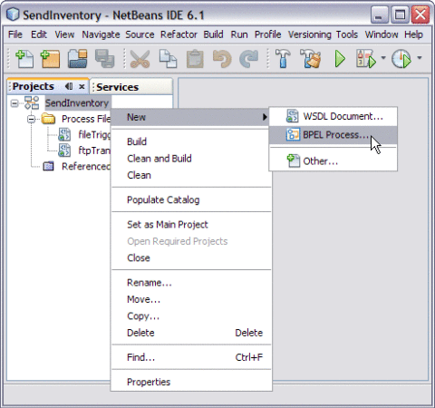
This opens the New BPEL Process wizard.
-
Type the File Name in the File Name field.
For example, sendInventory
-
Click Finish.
Note –-
In the Projects window, the IDE adds a sendInventory.bpel node under the Process Files node.
-
The sendInventory.bpel file is open in the BPEL Designer.
-
The Properties window is open.
-
Choose Window —> Properties, if the Properties window is not visible.
-
The Navigator window is open showing the BPEL Logical View of the BPEL Process document.
-
 To Add a Partner Link
-
Select the Partner Link from the Projects tab.
For example, fileTrigger.wsdl
This is the Input WSDL.
-
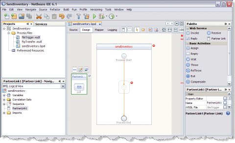
Drag and drop the FILE WSDL Document to the left panel of the design area.
For example, fileTrigger.wsdl
-
Select the Partner Link from the Projects tab.
For example, ftpTransferr.wsdl
This is the Output WSDL.
-
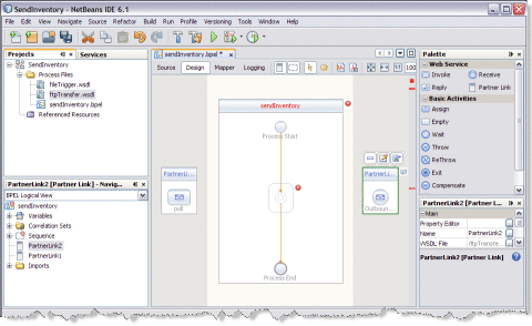
Drag and drop FTP WSDL Document to the right panel of the design area.
For example, ftpTransferr.wsdl
 To Add Web Services and Basic Activities
Drag and Drop the following Web Services:
-
Receive
-
Invoke
Drag and Drop the Basic Activities : Assign.
-
Select the Web Service : Receive in the Web Service section of the Palette.
-
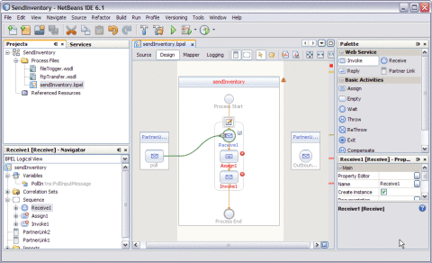
Drag the selection to the sendInventory Process box in the design area between the Process Start and the Process End activities.
The IDE provides the visual clues to show an appropriate location to drop the selection.
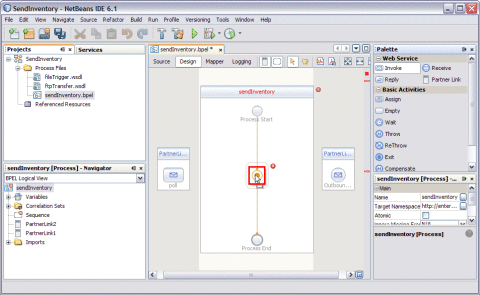
This action places a Web Service : Receive1 in the Design view.
-
Select the Basic Activities : Assign in the Basic Activities section of the Palette.
This action places a Assign activity called Assign1 in the Design view.
-
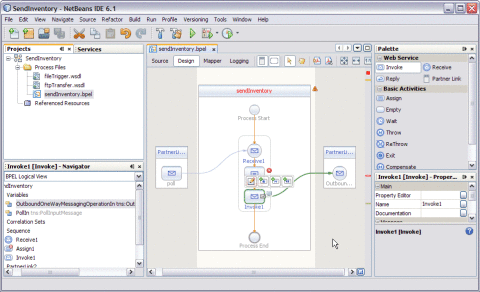
Select the Web Service : Invoke in the Web Service section of the Palette.
This action places a Assign activity called Invoke1 in the Design view.
-
Click Save All.
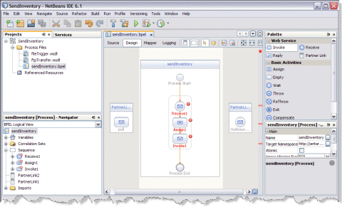
Note –In the diagram, a red cross next to an element means that the element has not passed validation and the output contains errors. Edit each Sequence to pass validation.
The icon symbolizes the Web Services that can be edited.
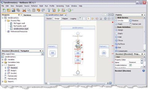
 To Edit Web Service : Receive1
-
Click Web Service — Receive1 and click Edit.
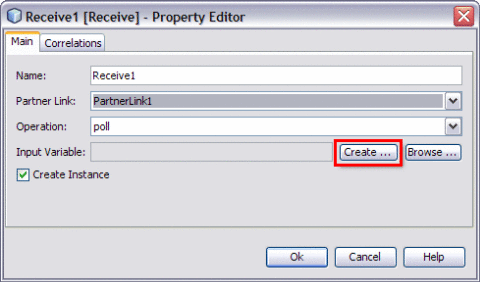
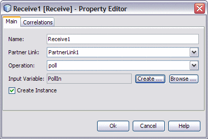
This opens the Receive1 [Receive] - Property Editor.
-
Select the properties from the Main tab. In this example, select PartnerLink1 from the drop-down list.
The IDE populates poll against the Operation field.
-
Create a New Input Variable.
Perform the following:
-
Click the Create button next to the Input Variable field.
This opens the New Input Variable dialog box.
-
The default values assigned in the Name, Type, and Scope fields are populated for the variable.
The value against the Name field can be changed.
-
Click OK.
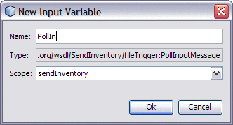
Input Variable — PollIn
-
-
Click OK to close the Receive1 [Receive] - Property Editor.
-
Click Save All.
 To Edit the Web Service : Invoke1
-
Click Web Service — Invoke1 and click Edit.
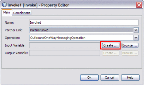
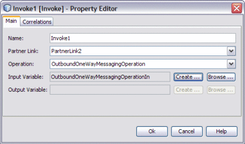
This opens the Invoke1 [Invoke] - Property Editor.
-
Select the properties from the Main tab. In the current example, select PartnerLink2 from the drop-down list.
The IDE populates OutboundOneWayMessagingOperation against the Operation field .
-
Create a New Input Variable.
Perform the following:
-
Click the Create button next to the Input Variable field.
This opens the New Input Variable dialog box.
-
The default values assigned to the Name, Type and Scope fields are populated for the variable.
The value against the Name field can be changed.
-
Click OK.
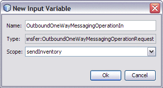
The Invoke1 [Invoke] — Property Editor is displayed as shown.
-
-
Click OK to close the Receive1 [Receive] - Property Editor.
-
Click Save All.
 To Edit the Basic Activities : Assign1
-
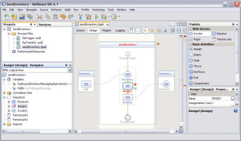
Double-click the Basic Activity : Assign1.
This displays the BPEL Mapper window.
-
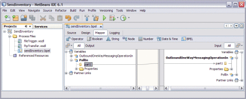
Expand the node in the Source tree pane (the left pane) of the BPEL Mapper under Output —> Variables.
For example, PollIn
A part1 node appears under the PollIn node.
-
Expand the node in the Destination tree pane (the right pane) of the BPEL Mapper under Input —> Variables.
For example, OutboundOneWayMessagingOperationIn
A part1 node appears under the OutboundOneWayMessagingOperationIn node.
-
Select the node in the Source tree pane.
For example, PollIn — part1
-
Drag the selection and map it to the node in the Destination tree pane.
For example, OutboundOneWayMessagingOperationIn — part1
-
Map the following Input and Output Variables
part1 — part1
-
Click Save All.
-
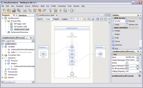
Click the Design tab.
The final output is as shown in the illustration.
-
Right-click the project node. Select Clean and Build.
For example, sendInventory
The following message is displayed after the build.
BUILD SUCCESSFUL (total time: 1 seconds).

-
Click Save All.
- © 2010, Oracle Corporation and/or its affiliates
