Using the LDAP Binding Component in a Project
The topics in this document provides information about LDAP Binding Component.
For more information about working with the NetBeans IDE, see the http://www.netbeans.org page on the NetBeans web site.
What You Need to Know
These topics provide information about the functional behavior of LDAP Binding Component.
What You Need to Do
These topics provides instructions on the following:
Tutorial Overview
This tutorial helps you create a new OpenESB component called LDAP Binding Component.
It also shows you how to create a LDAP Binding Component project that accesses a LDAP server. It illustrates how to implement the method for requesting and displaying data from a LDAP server.
This component implements all the required interfaces from the JBI 1.0 specification.
The LDAP browser project is an application that holds an implementation of a data provider (for example, LDAPTableDataProvider). In addition to this, the application demonstrates how to pass a request to the server and how to specify the set of attributes to be received from the server.
Tutorial Requirement
Read the sections thoroughly before trying to execute the Binding Component.
Software Needed for the Tutorial
Note –
Before installing GlassFish ESB V2, check whether the Sun JDK and SDK files are installed.
LDAP Binding Component assumes that the following are configured on the target resource.
-
A JCA container, tested with GlasshFish V2.0 installer
-
LDAP Web Browser — This browser is used to view the Output
For example, Softerra LDAP Browser
Tutorial Plan
-
Create a BPEL Module project using the New Project wizard.
-
Create the following WSDL Document for the BPEL Module.
-
LDAP WSDL
-
SOAP WSDL
Note –Test Cases are not required for File Binding Component and JMS.
-
-
Create a Composite Application project.
-
Add the BPEL Module project (*.jar) as a JBI Module to the Composite Application project.
-
Build the Composite Application project. Ensure that the Application Server is started.
-
Deploy the Composite Application project to the Application Server.
-
Create a Test Case.
-
Run the Test Case.
-
(Optional) Debug the BPEL process.
Debug is invoked when the Test Case fails.
Follow the outlined procedure to build a BPEL process.
LDAP Binding Component Project in a Nutshell
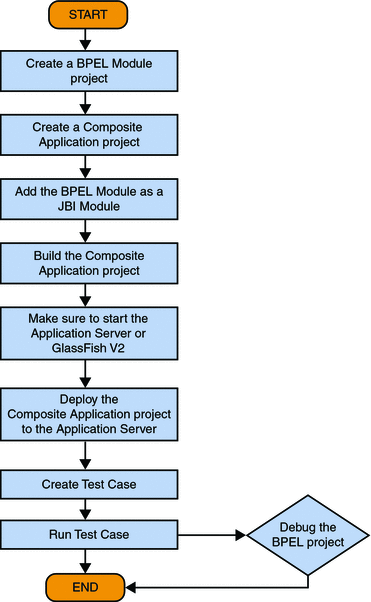
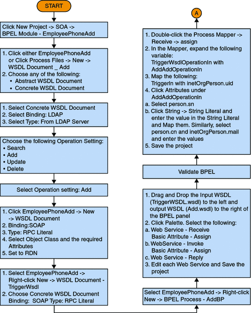
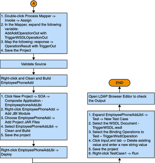
The following illustration explains the procedure of creating a LDAP Binding Component project.
Flowchart 1
Flowchart 1 (Continued)
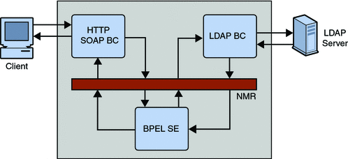
Functional Architecture of LDAP Binding Component
The LDAP Binding Component provides a comprehensive solution for configuring and connecting to the LDAP server within a JBI environment. The design-time component is a NetBeans IDE 6.1 module that plugs into the NetBeans Enterprise Pack project system. The runtime component provides the physical connectivity between the Normalized Message Router in the JBI framework and the external LDAP server. The runtime component can act as a service provider, supporting Outbound (Sending requests to the LDAP server from the JBI framework).
This component implements all the required interfaces from the JBI 1.0 specification.
Downloading GlassFish ESB Installer
This topic describes the procedure to download GlassFish ESB installer. The installer is available from the following location:
Visit the following links to get more information.
-
Installing the JDK Software and setting up JAVA_HOME on the Windows System - http://wiki.open-esb.java.net/Wiki.jsp?page=Inst_jdk_javahome_t.txt
-
Installing GlassFish ESB using the GlassFish ESB Installer - http://wiki.open-esb.java.net/Wiki.jsp?page=Inst_caps_t.txt
Downloading and Installing the JAR Files and the NBM Files
This topic describes the steps to download and install the required JAR and NBM files for the Database Binding Component.
 To Install the JAR Files in the LDAP Binding Component
-
Download ldapbc.jar files to a location on disk.
-
StartNetBeans IDE.
-
Click Services tab -> Servers —> GlassFish V2 -> Start.
-
Right-click JBI —> Binding Components.
-
Right-click on Binding Components node. Select Install to browse to the files downloaded in step 1.
-
Right-click on the installed binding component. Select Start.
 To Install the NBM Files in LDAP Binding Component
-
Download the org-netbeans-modules-wsdlextensions-ldap.nbm files to a location on disk.
-
Start NetBeans IDE.
-
Click Tools —> Plugins.
-
Click on the Downloaded tab.
-
Click Add Plugins to browse for the files downloaded in step 1.
-
Click Install. Follow the prompt to complete installing the NBM files.
Starting the GlassFish V2 Application Server
The GlassFish Application Server is installed when GlassFish ESB is configured. NetBeans starts the Application Server when needed.
 To Start the GlassFish V2 Application Server
Before You Begin
Choose Window —> Services, if the Services tab is not visible.
-
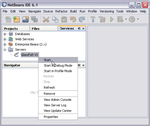
Click the Services tab and expand the Servers node.
The Servers node must contain a GlassFish V2 subnode.
-
Right-click the GlassFish V2 node. Select Start.
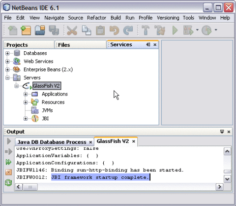
The Output window displays log information generated during the application startup.
Note –Choose Window —> Output —> Output, if the Output window is not visible.
The following message in the Output console window is an indication that the application server is listening.
JBI framework startup complete.
Note –A green arrow badge on the GlassFish Application Server node indicates the server is listening.
GloassFish V2
The GlassFish V2 server is invoked when an application is deployed to the GlassFish Application Server.
 To Start the JBI Components
-
Expand GlassFish —> JBI —> Binding Components.
-
Right-click on sun-ldap-binding. Click Start.
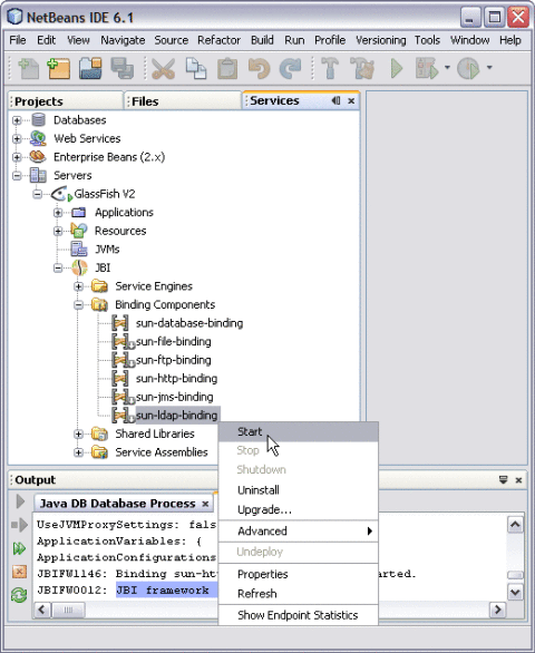
The action enables sun-ldap-binding.
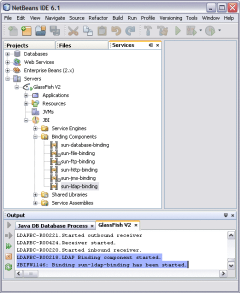
The Output console displays a confirmation message.
Binding sun-ldap-binding has been started.
Creating a BPEL Module Project For the Add Feature
In this scenario, an Object Class and an Attribute is added and are identified as Input and Output, respectively.
 To Create a BPEL Module Project
-
Choose File —> New Project from the main menu.
This opens the New Project wizard.
-
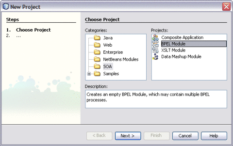
Select the SOA node from the Categories list.
-
Select the BPEL Module node from the Projects list.
-
Click Next.
-
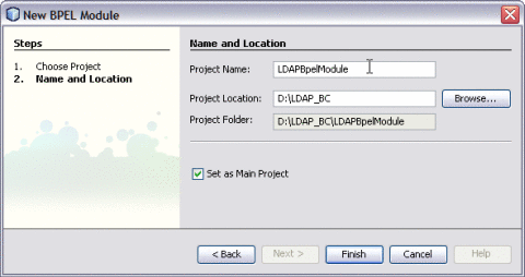
Type the Project Name in the Project Name field.
For example, LDAPBpelModule
-
Click Browse to navigate to the project location field.
The IDE stores the project files. This step is optional.
-
Click Finish.
A project node for the BPEL module project names LDAPBpelModule is created in the Projects window.
-
Click Save All.
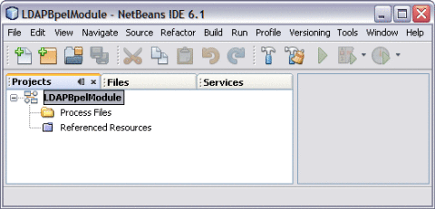
Creating a WSDL Document : Add Feature
In this section, create a WSDL Document using the Add feature. For example, AddWSDL.wsdl to the BPEL Module project. Use the Partner view of the WSDL editor to configure the components of the WSDL Document.
 To Create a WSDL Document : Add Feature
-
Expand the BPEL Module project node in the Projects tab.
For example, LDAPBpelModule
-
Right-click the project node or Process Files node. Select New —> WSDL Document...
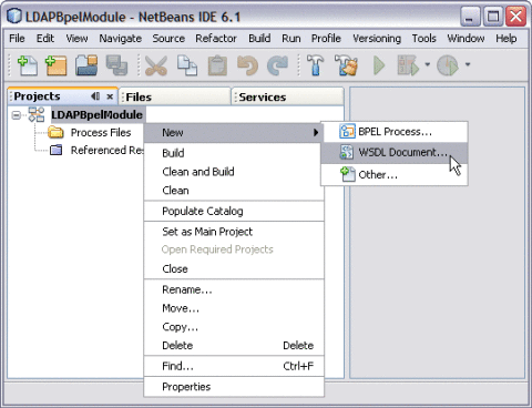
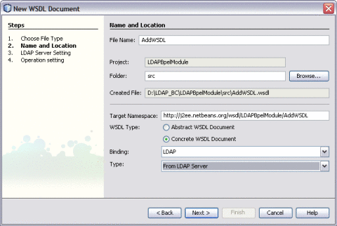
This opens the New WSDL Document wizard.
-
Type the File Name in the File Name field.
For example, AddWSDL.wsdl
-
Select Concrete WSDL Document.
-
Choose the Binding — LDAP from the drop-down list.
-
Choose any one of the following Types from the drop-down list.
-
From LDAP Server
-
From LDIF File
-
-
Choose Type — From LDAP Server from the drop-down list.
-
Click Next.
-
Enter the Root DN and LDAP Server URL.
DN: base object entry search relative to
For example, the Root DN is dc=sun,dc=com and LDAP Server URL is ldap://server ip address:port number.
-
Click Advanced.
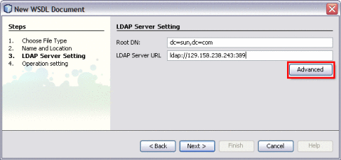
This action displays the Advanced Login dialog box.
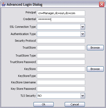
For example,
-
Principal: cn=Manager,dc=sun,dc=com
-
Credentials: *******
-
-
Click OK to close the Advanced Login Dialog.
-
Click Next.
The New WSDL Document — Operation Setting dialog box opens.
Note –You can perform any one of following operations.
-
Search
-
Add
-
Update
-
Delete
-
-
Click the Add tab.
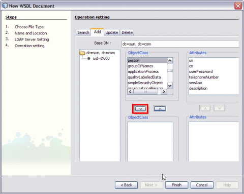
Select the following Object Class:
Click the down arrow to move them from the top-left pane to the bottom-left pane.
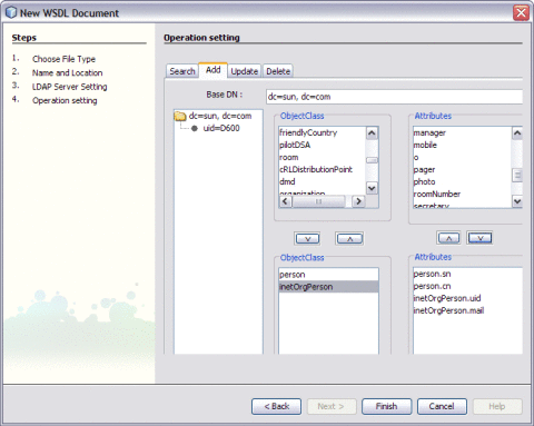
Note –The attributes related to the schema are selected.
Each schema is made up of a set of attributes.
For example,
-
person — person.sn and person.cn
-
inetOrgPerson — inetOrgPerson.uid and inetOrgPerson.mail
They are represented as follows:
-
sn — Surname
-
cn — Common Name
-
uid — Unique id
-
mail — Email
schemaname.Attributename
-
Note –Use the down arrow to move the selected Object Class or Attributes from the top-left pane to the bottom-left pane. Use this to also move from the top-right pane to the bottom-right pane.
-
-
Set any one of the Attributes to Relative Distinguished Name (RDN).
A Relative Distinguished Name (RDN) is a component of the distinguished name.
For example, cn=John Doe, ou=People is a RDN relative to the root RDN dc=sun.com.
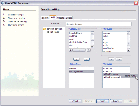
For example, Set inetOrgPerson.uid = RDN
-
Click Finish.
The illustration is as shown.
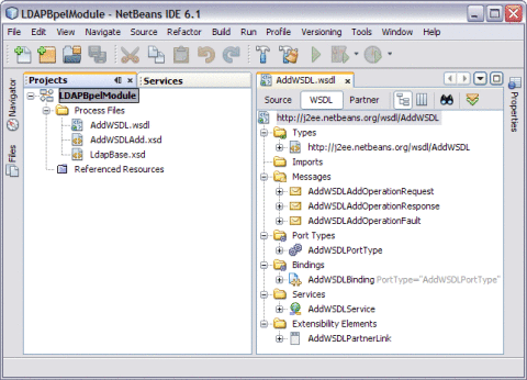
A tree structure is formed as follows:
WSDL View
-
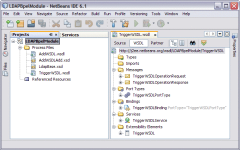
In the WSDL view of the WSDL Editor, the WSDL file appears as a tree component or a series of columns.
-
The WSDL view has two subviews: tree view and column view. To switch between the subviews, use the buttons in the WSDL Editor toolbar.
-
The main nodes in the WSDL view correspond to the major elements in a WSDL file.
-
Types: This node enables you to import XML schemas and to add inline schemas.
-
Imports: This node enables you to import WSDL files.
-
Messages: This node enables you to create, edit, and delete messages.
-
Port Types: This node enables you to create, edit, and delete port types.
-
Bindings: This node enables you to create, edit, and delete bindings.
-
Services: This node enables you to create, edit, and delete services.
-
Extensibility Elements: This node enables you to add the following extensibility elements: partner link types, properties, and property aliases.
-
Some of the nodes in the WSDL view allow you to add extension attributes.
-
Right-click the node and choose Add Extension Attribute.
-
Specify the name and namespace in the Add Extension Attribute dialog box.
-
Specify the value from the Properties window after adding the attribute.
-
Right-click the node and choose Remove Attributes to delete the attribute.
Create a WSDL Document For Type : SOAP
In this section, add a WSDL document, for example, TriggerWsdl.wsdl to the BPEL Module project. The Partner view of the WSDL editor to configure the components of the WSDL document.
 To Create a WSDL Document : SOAP
-
Expand the project node in the Projects window. Right-click the BPEL Module node or Process Files node. Choose New —> WSDL Document...
For example, LDAPBpelModule
This opens the New WSDL Document wizard.
-
Type the File Name in the File Name field.
For example, TriggerWSDL.wsdl
-
Select Concrete WSDL Document.
-
binding
Defines the message format and protocol details for a port type.
-
service
Indicates the binding type to be used and the method to access the database resource.
-
-
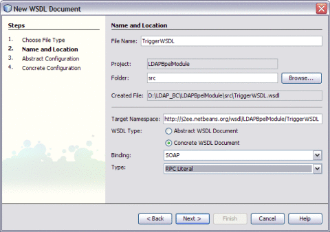
Choose the Binding — SOAP from the drop-down list.
-
Select any one of the following Type.
If you select the SOAP binding type, then select any one of the following binding subtypes:
-
RPC Literal: The operations are RPC oriented (that is, messages contain parameters and return values). Each message part uses an element or type attribute to refer to a concrete schema definition.
-
Document Literal: The operations are document oriented (that is, messages contain one or more documents). Each message part uses an element or type attribute to refer to a concrete schema definition.
-
RPC Encoded: The operations are RPC oriented (that is, messages contain parameters and return values). Each message part uses a type attribute to refer to an abstract type.
-
-
Choose Type — RPC Literal from the drop-down list.
-
Click Next.
This action displays the New WSDL Document dialog box.
-
Choose the Operation Type from the drop-down list.
The WSDL Editor is used to create, edit, and delete port types.
The WSDL Editor supports the following operation types. There are two Operation Types.
-
Request-Response Operation: The operation receives a message as input, and sends a message as output.
-
One-Way Operation: The operation receives a message as input.
Each message contains one or more logical parts. Specify the name and the type of content for each part.
If you change the name of a port type or operation, then the WSDL Editor renames all occurrences in the same file. Right-click the component node to rename all occurrences in the associated XSD, WSDL, and BPEL files. Choose Refactor —> Rename.
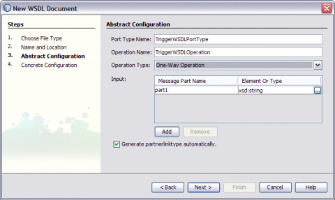
When Operation Type is One-Way Operation. The following illustration demonstrates when the operation type is chosen as One-Way Operation.
Note –-
Click the ellipses (...) button to select an Element or Type.
-
Enter both the Input and Output Message Part Names for the Request-Response Operation.
The default value of the Input and Output Message Part Names is set as xsd:string.
-
Click Add to another Message Part Name as the Input.
This selects the checkbox Generate partnerlinktype automatically.
Note –Click Remove to delete the Message Part Name as the Input.
See Steps 11 through 15.
-
-
Select Operation Type : Request-Response Operation from the drop-down list.
Note –Port Type Name and Operation Name are populated from the previous wizard.
-
Click the ellipses (...) to select the Element or Type.
Enter a Message Part Name for both Input and Output — TriggerIn and TriggerOut, respectively.
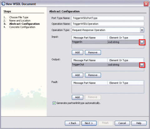
This action displays the Select Element or Type dialog box.
Retain the same values for Element or Type both for Input and Output as xsd:string.
-
Click Next.
The New WSDL Document — Concrete Configuration window is displayed.
Verify the Concrete Configuration.
-
Click Finish.
Creating a BPEL Process
In this section, add a BPEL process file. For example, AddBPEL.bpel. You will also learn to add a partner link and associate three activities to the BPEL process file. Create a BPEL Module project to orchestrate.
 To Create a BPEL Process
-
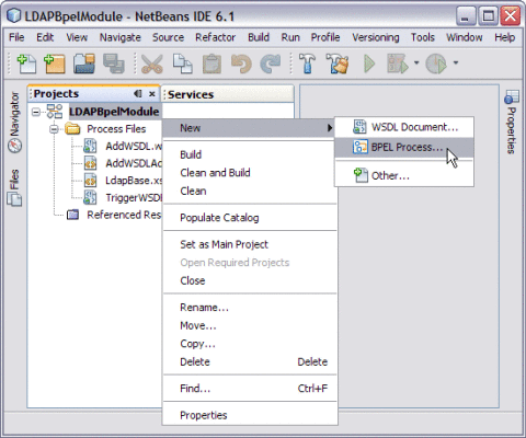
Expand the project node in the Projects window. Right-click the node or Process Files node. Choose New —> BPEL Process...
For example, LDAPBpelModule
This opens the New BPEL Process wizard.
-
Type the Filename in the File Name field.
For example, AddBPELProcess
-
Click Finish.
Note –-
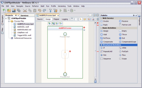
In the Projects window, the IDE adds a AddBPELProcess.bpel node under the Process Files node.
-
The AddBPELProcess.bpel file is open in the BPEL Designer.
The BPEL Designer has two views: Source and Design.
-
The Properties window is open.
-
Choose Window —> Properties if the Properties window is not visible.
-
The Navigator window shows the BPEL Logical View of the BPEL Process document.
-
 To Add a Partner Link
-
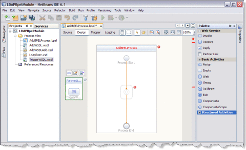
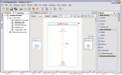
Select the Partner Link from the Projects tab. Drag and drop it to the left panel of the design area.
For example, TriggerWSDL.wsdl
This is the Input WSDL.
-
Select the Partner Link from the Projects tab. Drag and drop it to the right panel of the design area.
For example, AddWSDL.wsdl
This is the Output WSDL.
 To Add a Web Service and Basic Activities
Drag and Drop the following Web Services:
-
Receive
-
Invoke
-
Reply
Drag and Drop the Basic Activities : Assign.
-
Select the Web Service : Receive in the Web Service section of the Palette.
-
Drag the selection to the box in the design area between the Process Start and the Process End activities.
For example, BPEL Process box : AddBPELProcess
The IDE provides the visual clues to show an appropriate location to drop the selection.
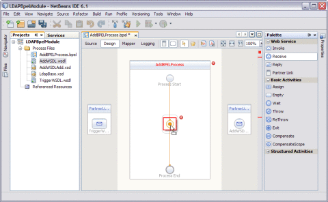
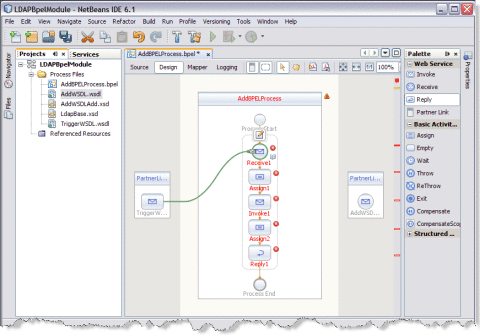
This action places a Web Service Receive called Receive1 in the Design view.
-
Select the Basic Activities. Choose Assign in the Basic Activities section of the Palette.
This action places a Assign activity called Assign1 in the Design view.
-
Drag the selection to the AddBPELProcess box in the design area, between the Process Start and the Process End activities.
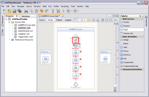
Note –Repeat steps 1 through 4 to select Invoke1, Assign2, and Reply1.
Choose the following:
-
Select the Web Service : Invoke and Basic Activities : Assign.
-
Select the Web Service : Reply.
The icon symbolizes that the Web Services can be edited.
Note –In the diagram, a red cross next to an element means that the element has not passed validation and the output contains errors. Edit each Sequence to pass validation.
-
 To Edit the Web Service : Receive1
-
Click Web Service — Receive1 and click Edit.
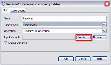
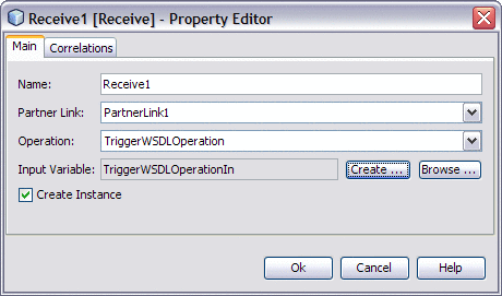
This opens the Receive1 [Receive] - Property Editor.
-
Select the properties of this service from the Main tab. Select PartnerLink1.
The Operation drop-down list refreshes to display TriggerWSDLOperation.
-
Create a new input variable.
Perform the following:
-
Click the Create button next to the Input Variable field.
This opens the New Input Variable dialog box.
-
The Name, Type, and Scope variable fields are refreshed with their default values.
Change the value in the Name field.
-
Click OK.
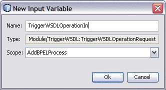
Note –-
All the fields are populated with the assigned values.
The Input Variable is TriggerWSDLOperationIn
-
Create Instance check-box is checked, by default.
-
-
Click OK to close the Receive1 [Receive] - Property Editor.
-
Save the project.
 To Edit the Web Service : Invoke1
-
Click Web Service — Invoke1 and click Edit.
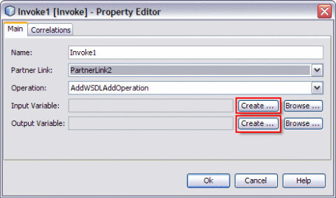
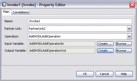
This opens the Invoke1 [Invoke] - Property Editor.
-
Select the properties from the Main tab. Select PartnerLink2 from the drop-down list.
The Operation drop-down list refreshes to display AddWSDLAddOperation.
-
Follow these steps to create a new input and an output variable.
-
Click the Create button next to the Input Variable field.
This opens the New Input Variable dialog box.
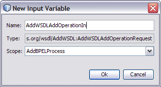
The Name, Type, and Scope variable fields are refreshed with their default values.
You can also change the value in the Name field.
-
Click OK to close the New Input Variable dialog box.
-
Click the Create button next to the Output Variable field.
This opens the New Output Variable dialog box.
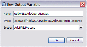
The Name, Type, and Scope variable fields are refreshed with their default values.
You can also change the value in the Name field.
-
Click OK to close the New Output Variable dialog box.
Note –All the fields are populated with the assigned values.
Select the following Variables:
-
Input Variable : AddWSDLAddOperationIn
-
Output Variable : AddWSDLAddOperationOut
-
-
Click OK to close the Invoke1 [Invoke] - Property Editor.
-
Save the project.
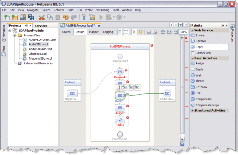
 To Edit the Web Service : Reply1
-
Click Web Service : Reply1. Click Edit.
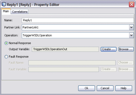
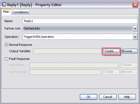
This opens the Reply1 [Reply] - Property Editor.
-
Select the properties from the Main tab. Select PartnerLink1 from the drop-down list.
The Operation drop-down list refreshes to display TriggerWSDLOperation.
-
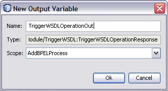
Follow the steps to create a New Output Variable.
-
Click OK to close the Reply1 [Reply] - Property Editor.
 To Edit the Basic Activities : Assign1
-
Double-click the Basic Activity : Assign1.
This displays the BPEL Mapper window.
Note –Choose Window —> Other —> BPEL Mapper from the main menu if the BPEL Mapper window is not visible.
-
Expand the node in the Source tree pane (the left pane) of the BPEL Mapper under Output —> Variables.
For example, TriggerWSDLOperationIn
A Trigger1n node appears under the TriggerWSDLOperationIn node.
-
Expand the node in the Destination tree pane (the right pane) of the BPEL Mapper under Input —> Variables.
For example, AddWSDLAddOperationIn
A request node appears under the AddWSDLAddOperationIn node.
-
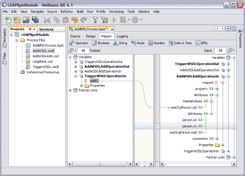
Select the node in the Source tree pane. Drag the selection and map it to the node in the Destination tree pane.
For example,
-
Source tree pane: TriggerWSDLOperationIn — Trigger1n
-
Destination tree node: AddAddOperationIn — request — attributes — MainAttribute — inetOrgPerson.uid
Map the following:
TriggerIn — inetOrgPerson.uid
-
-
Click Save All.
-
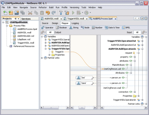
Expand the node in the Destination tree pane (the right pane) of the BPEL Mapper under Input —> Variables.
For example, AddWSDLAddOperationIn
-
Select request — attributes — Attributes
-
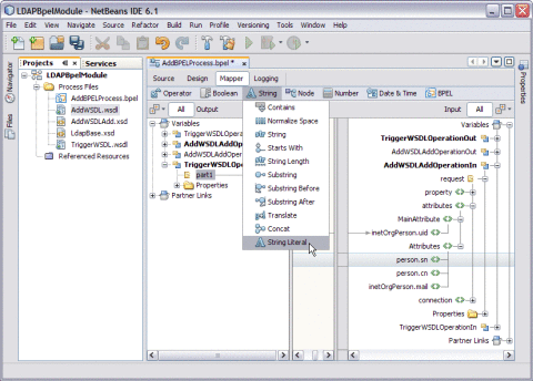
Select person.sn.
-
Click String and select String Literal from the drop-down list.
-
Enter the values in the String Literal and map the String Literal with person.sn.
For example, person.sn = Joe, where sn = surname and person.cn = Jane where cn = common name
Note –Similarly, select person.cn and follow steps b and c.
-
-
-
Click Save All.
-
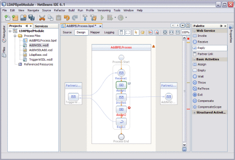
Click the Design tab.
Note –A red icon marked against Basic Activities — Assign1 is not shown.
 To Edit the Basic Activities : Assign2
-
Double-click the Basic Activity : Assign2.
This displays the BPEL Mapper window.
Note –Choose Window —> Other —> BPEL Mapper from the main menu if the BPEL Mapper window is not visible.
-
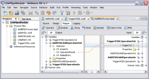
Expand the node in the Source tree pane (the left pane) of the BPEL Mapper under Output — Variables.
For example, AddWSDLAddOperationOut
Expand response — OperationResult.
-
Expand the node in the Source tree pane (the right pane) of the BPEL Mapper under Input — Variables.
For example, TriggerWSDLOperationOut
-
Map the following variables
For example, OperationResult — TriggerOut
-
Click Save All.
-
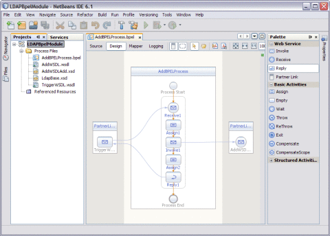
Click the Design tab.
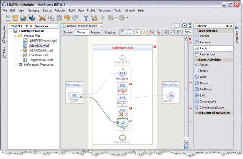
The final output is as shown in the illustration.
-
Right-click the BPEL Module and select Clean and Build.
For example, LDAPBpelModule
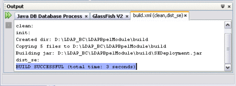
The following message is displayed.
BUILD SUCCESSFUL (total time: 3 seconds).
-
Click Save All.
Creating a Composite Application Project
Add the JBI module to the deployment project before deploying the BPEL Module project. Deploying the project makes the service assembly available to the application server. This allows its service units to execute their functionality.
 To Create a Composite Application Project
-
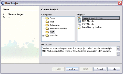
Choose File —> New Project.
This opens the New Project wizard.
-
Select the SOA node from the Categories list.
-
Select the Composite Application node from the Projects list.
-
Click Next.
-
Type the Project Name in the Project Name field.
For example, AddCompApp
-
Click Finish.
The Projects window now contains a project node for a Composite Application project named AddCompApp.
-
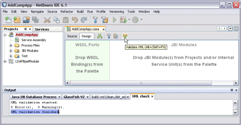
Click the Validate XML button.
This action invokes an XML check and displays the following message in the XML check console.
XML validation finished.
-
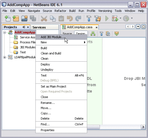
Right-click either the Composite Application or the JBI Modules.
For example, AddComositeApp
-
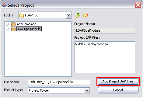
Select Add JBI Module.
-
Select the BPEL Module Project. Click Add Project JAR Files.
For example, LDAPBpelModule
In the current example, the Project JAR file is build/SEDeployment.jar.
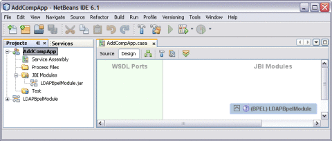
The JAR file is added and is as shown in the illustration.
-
Click Save All.
Note –Ensure to following services are started.
-
GlassFish V2 Application Server
-
JBI Binding Component (sun-ldap-binding)
-
-
Right-click the Composite Application node. Select Clean and Build.
For example, AddCompApp
The CASA Editor displays the build associated with AddCompApp.
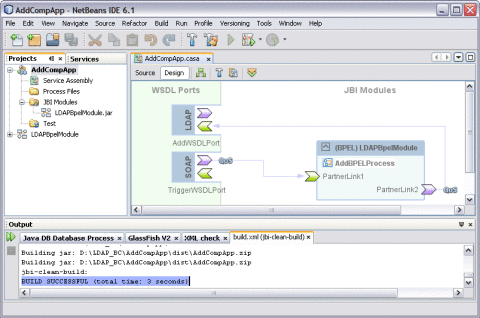
A success message is displayed in the Output window:
BUILD SUCCESSFUL (total time: 3 seconds)
-
Click Save All.
Deploying a Composite Application
This section lists the procedure to deploy the composite application.
Tip –
Start the Sun Java System Application Server before deploying the project.
 To Deploy a Composite Application
-
Right—click Composite Application project node from the Projects tab.
For example, AddCompAppl
-
Select Deploy.
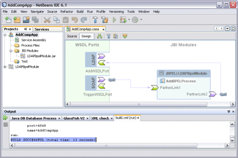
After successful deployment of the project the Output window displays the following message:
BUILD SUCCESSFUL (total time: 13 seconds).
Testing the Composite Application
This section lists the procedure to test the deployed application.
 To Test the Composite Application
-
Expand the Composite Application project. Click Test.
For example, AddCompApp
-
Right-click to select New Test Case.
-
Enter the Test Case Name.
For example, AddTest
-
Click Next.
-
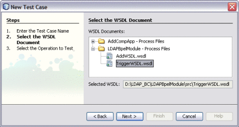
Select the WSDL Document.
-
Select one WSDL Document from the BPEL Module.
In the current example, the WSDL Document is TriggerWSDL.wsdl and the BPEL Module is LDAPBpelModule — Process Files.
Note –Select one WSDL Document.
-
Click Next.
-
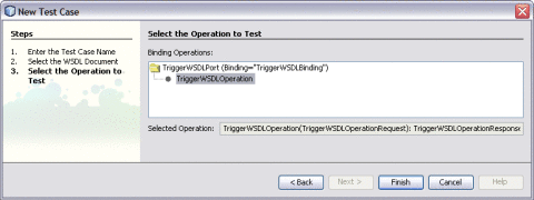
Select one Operation to text file from the Process Files.
In the current example, the Operation to Text file is TriggerWSDLOperation and the Process File is TriggerWSDLPort (Binding=”TriggerWSDLBinding”).
Note –Select one Operation to Text file.
-
-
Click Finish.
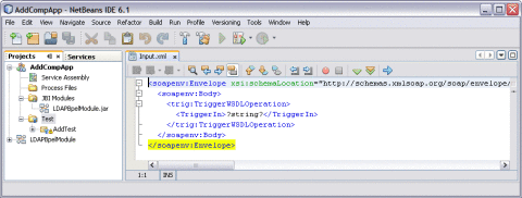
This displays the Source code.
-
Enter the string value.
string = Jane
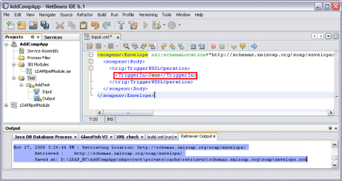
The Output console displays Retrieve.xml when you enter a string value in the input.xml window.
-
Right-click the Test Case and click Run.
For example, AddTest
A confirmation dialog box prompts to overwrite an existing Output.
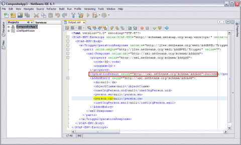
-
Click Yes.
The Output is as shown in the illustration.
For a demo on the Add feature, visit the following URL:
http://wiki.open-esb.java.net/Wiki.jsp?page=LDAPAddFeatureScreencast
Source View
Right-click a node and choose Go To —> Source.
The Source view appears with the cursor positioned at the beginning or end of the component's block.
-
The top of the Source Editor has a tab for each open document. Each tab shows the name of the document.
Note –If the document has been modified and has not been saved, then an asterisk (*) appears after the name. You can right-click a tab to access various commands.
-
A toolbar is located at the top of the Source Editor window.
-
Source code displayed in the Source Editor is syntactically colored.
-
The Source Editor status line is located beneath the horizontal scroll bar. To toggle between insert mode and overwrite mode, use the Insert key.
In the Source view, the underlying XML source code appears. You can directly edit the XML.
Design View: Notification
The Design view displays the results of both real-time and explicit validation in callout windows on the diagram and the error stripe.
In the illustration,
Note –
A red cross next to an element on the diagram means that the element has not passed validation and the output contains errors.
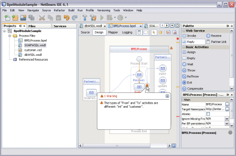
A yellow triangle with an exclamation mark means that the element has not passed validation and the output contains warnings.
A red cross in the Design view means there are both errors and warnings.
If you click the cross or the triangle, a callout window lists errors and warnings.
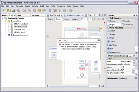
The callout window displays messages related to validation in accordance with the criteria listed above. Messages related to real-time validation are constantly updated.
In the Design view, the error stripe displays the validation results. The error stripe is a strip to the right of the scroll bar that contains red marks if some elements have not passed validation. The error stripe represents the entire diagram, not just the portion that is currently displayed. This stripe helps users to immediately detect any errors in the BPEL process without having to scroll through the entire diagram. Click a red mark to jump to the element that causes problems. If no errors are detected, the small square in the error stripe is green.
Create a WSDL Document : Search
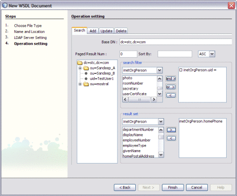
In this section, the user sets to search using the search filter. The input for the uid is provided from the HTTP/SOAP WSDL and the response is routed to the SOAP reply.
For steps, see the following links:
-
Create a WSDL Document For Type : SOAP.
-
Click the Search tab.
In the current example, the selected Object Class is inetOtgPerson.
Search Filter
-
Select Search Filter — inetOrgPerson from the drop-down list.
-
Select uid from the Search Filter list.
-
Click the > arrow.
inetOrgPerson.uid = is moved to the right pane.
Result Set
Tip –Entries with respect to inetOrgPerson are populated both in the Search Filter and Result set.
-
Select Result Set — homePhone from the drop-down list.
-
Click > arrow to move the selected entry to the right pane.
-
-
Click Finish.
-
For a demo on Search, visit the following URL:
http://wiki.open-esb.java.net/Wiki.jsp?page=LDAPSearchFeatureScreencast
Create a WSDL Document : Update Feature
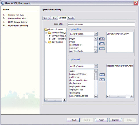
In this section, the user sets to use the Update feature.
For steps, see the following links:
-
Create a WSDL Document For Type : SOAP.
-
Click the Update tab.
In the current example, the selected Object Class is inetOtgPerson.
-
Select Update Filter — inetOrgPerson from the drop-down list.
-
Select uid from the Update Filter list.
-
Click the > arrow.
inetOrgPerson.uid = is moved to the right pane.
Update Filter
Update Set
Tip –Entries with respect to inetOrgPerson are populated both in the Update Filter and Update set.
-
Select Update Set — homePhone from the drop-down list.
-
Click > arrow to move the selected entry to the right pane.
-
-
Click Finish.
-
For a demo on the Update feature, visit the following URL:
http://wiki.open-esb.java.net/Wiki.jsp?page=LDAPUpdateFeatureScreencast
Create a WSDL Document : Delete Feature
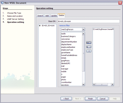
In this section, the user sets the Delete feature.
For steps, see the following links:
-
Create a WSDL Document For Type : SOAP.
-
Click the Delete tab.
In the current example, the selected Object Class is inetOtgPerson.
-
Select Remove Filter — inetOrgPerson from the drop-down list.
-
Select the entry from the Remove Filter list.
For example, uid
-
Click the > arrow.
-
inetOrgPerson.uid = is moved to the right pane.
Remove Filter
-
-
Click Finish.
-
- © 2010, Oracle Corporation and/or its affiliates

