| Skip Navigation Links | |
| Exit Print View | |

|
Sun Blade 6000 Virtualized Multi-Fabric 10GbE M2 Network Express Module User's Guide Sun Blade 6000 Virtualized Multi-Fabric 10GbE M2 Network Express Module Documentation Library |
| Skip Navigation Links | |
| Exit Print View | |

|
Sun Blade 6000 Virtualized Multi-Fabric 10GbE M2 Network Express Module User's Guide Sun Blade 6000 Virtualized Multi-Fabric 10GbE M2 Network Express Module Documentation Library |
About This Documentation (PDF and HTML)
Overview of Sun Blade 6000 Virtualized Multi-Fabric 10GbE M2 NEM User's Guide
Features of the Sun Blade 6000 Virtualized Multi-Fabric 10GbE M2 NEM
Performing Hot Plug Insertion and Removal
Installing or Replacing the Virtualized M2 NEM
Installing and Removing SFP+ Optical Transceiver Modules
Booting Over the Virtualized M2 NEM 10-Gigabit Ethernet Port
Booting over the Network With an x86 Blade Server
Booting over the Network With a SPARC Blade Server
Installing and Configuring the hxge Driver on a Solaris SPARC or x86 Platform
How to Configure the Network Host Files
Configuring the hxge Device Driver Parameters
Configuring the Jumbo Frames Feature
Installing and Configuring the hxge Driver on a Linux Platform
Installing and Removing the Driver on a Linux Platform
Configuring the Network Interface
Checking and Testing the hxge Device
Changing the hxge Driver Configuration
Installing and Configuring Drivers on a Windows Platform
Installing Drivers on a Windows Platform
Installing and Configuring Drivers on a VMware ESX Server Platform
Installing the ESX Server Drivers on an Existing ESX Server
Installing the ESX Server Drivers With a New ESX Installation
Configuring the Virtual NEM M2 Network Adapters
Accessing ILOM Documentation and Updates
Enabling Private and Failover Mode
This section provides information on the 10 GbE NIC functionality for the Virtualized Multi-Fabric 10GbE M2 NEM.
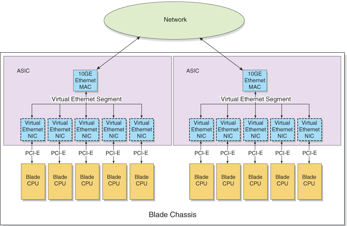
The Virtualized M2 NEM ASIC allows up to five hosts to share a single 10 GbE network port, with a dedicated PCIe endpoint for each host.
Shared I/O allows each server module to work as if a dedicated NIC connects the server module to the network. Each server module owns a virtual MAC that provides per-server-module statistics on Rx/Tx traffic. The MAC that interfaces to the 10 GbE network port is shared and is hidden from the server modules. Only the service processor can access and configure this port.
A Virtualized Multi-Fabric 10GbE M2 NEM contains two Virtualized M2 NEM ASICs, which can operate in two different modes: bandwidth mode and connectivity mode.
The Virtualized M2 NEM ASICs can operate in bandwidth mode where the Virtualized M2 NEM ASICs act without knowledge of each other. Each ASIC provides 10 GbE network access for the five hosts attached to it. Both SFP+ modules with optical cables should be installed, in order to provide 10 GbE connectivity for all ten server modules.

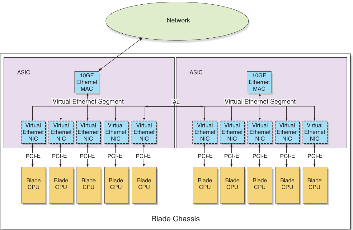
Two Virtualized M2 NEM ASICs can also be interconnected so that a single 10 GbE port can act as the shared I/O for 10 server modules (connectivity mode). The inter-ASIC link (IAL) extends the virtual Ethernet segment to all the server modules. An example of this configuration is shown in the following illustration.

When private mode is enabled through the NEM ILOM interface, all 10 GbE traffic passes between the NEM ASICs via the IAL. If SFP+ modules are installed or removed, there is no effect on the IAL status.
If private mode is enabled and failover mode is also enabled, private mode takes precedence, and removal or insertion of SFP+ modules has no effect.
See Enabling Private and Failover Mode for instructions on enabling private mode.
The IAL is enabled or disabled due to a combination of three different factors:
The number of SFP+ modules installed in the NEM
Whether or not the NEM has failover mode enabled
Whether or not the NEM has private mode enabled
The following table explains the IAL functionality:
Table 2 IAL Functionality
|
Refer to Enabling Private and Failover Mode for instructions on how to enable failover mode through the NEM service processor.
Note - If IAL is in failover mode and an additional SFP+ module is installed, you must install a network—connected cable into the newly installed SFP+ connector to ensure 10GbE connectivity for all server modules.
For example, in the following scenario, IAL will be dynamically disabled:
Ten server modules are installed in the Sun Blade 6000 chassis.
One SFP+ module is installed in the Virtualized M2 NEM.
Failover IAL mode is enabled.
One additional SFP+ module is installed.
The five server modules attached to the ASIC that is connected to the new SFP+ module will lose 10GbE connectivity unless a fiber optic cable is connected to the new SFP+ connector.