| Exit Print View | |
Sun Dual 10GbE PCIe 2.0 Fabric Expansion Module User’s Guide |

|
Documentation, Support, and Training
Understanding the Sun Dual 10GbE PCIe 2.0 Fabric Expansion Module
Power and Environmental Requirements
Hardware and Software Requirements
Installation Overview for Solaris Platforms
Installation Overview for Linux Platforms
Installation Overview for Microsoft Windows Platforms
Verify the Driver Version on a Solaris Platform
Remove the Driver From a Solaris Platform
Download and Install the Driver on a Linux Platform
Remove the Driver From a Linux Platform
Download and Install the Driver on a Microsoft Windows Platform
Remove the Driver From a Microsoft Windows Platform
Installing the Fabric Expansion Module
Verify the Installation in a Solaris SPARC System
Verify the Installation in a Solaris x86 System
Verify the Installation in a Linux System
Verify the Installation in a Microsoft Windows System
Create /etc/hostname.ixgbe# Files
Configure the Network Host Files With the ifconfig Command
Boot Over the Network Using PXE
Boot Solaris x86 and Linux Systems Over a 10GbE Network
Install the Solaris OS Over a 10GbE Network on SPARC Systems
Configuring the Driver Parameters
Driver Parameters for the Solaris OS
Set ixgbe Driver Parameters in the Solaris OS
Solaris OS Performance Variables
Improve Performance in the Solaris OS
Set Driver Parameters in Linux
Configure Jumbo Frames in Solaris OS
Configure Jumbo Frames in Linux
Configure Static VLANs in a Solaris Environment
Configure VLANs in a Linux Environment
The following instructions describe the basic tasks required to install the Sun Dual 10GbE PCIe 2.0 Fabric Expansion Module from Oracle inside a blade server module. Refer to your blade server’s system installation or server manual for detailed FEM instructions.
Halt and power off your system.
Attach the adhesive copper strip of the antistatic wrist strap to the server module chassis. Wrap the other end twice around your wrist, with the adhesive side against your skin.
Perform an orderly shutdown of the server module.
Remove the server module from the system chassis
Remove the cover from the server module.
Locate the FEM connectors on the server module.Ensure that you do use the correct connector. Look for the FEM label on the connectors.
 | Caution - Do not use the connectors labeled REM. |
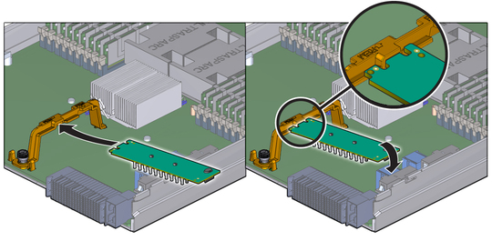
Slide the FEM card at an angle into the support bracket, then press it carefully into the connector.
Replace the cover on the server module.
Reinstall the server module into the chassis.
Refer to the server module’s service manual for specific instructions.
