Chapter 4 Logical Design
During the logical design phase of the solution life cycle, you design a logical architecture showing the interrelationships of the logical components of the solution. The logical architecture and the usage analysis from the technical requirements phase form a deployment scenario, which is the input to the deployment design phase.
This chapter contains the following sections:
About Logical Architectures
A logical architecture identifies the software components needed to implement a solution, showing the interrelationships among the components. The logical architecture and the quality of service requirements determined during the technical requirements phase form a deployment scenario. The deployment scenario is the basis for designing the deployment architecture, which occurs in the next phase, deployment design.
Analysis of Logical Architecture
A high-level logical architecture provides the basis for a low-level logical architecture. The high-level logical architecture needs to meet the business and technical needs that you previously established. The logical architecture is broken down according to the various applications that comprise the system as a whole and the way in which users interact with it. In general, the logical architecture includes Portal Server Secure Remote Access (SRA), high availability, security (including Access Manager, and Directory Server architectural components.
The high- and low-level architectures also need to account for any factors beyond the control of the portal, including your network, hardware failures, and improper channel design.
The low-level architecture specifies such items as the physical architecture, network infrastructure, Portal Desktop channel and container design and the actual hardware and software components.
High-Level Logical Architecture
The high-level logical architecture to supports both the business and technical requirements and addresses questions such as:
-
Does the proposed architecture support both the business and technical requirements?
-
Can any modifications strengthen this architecture?
-
Are there alternative architectures that might accomplish this?
-
What is the physical layout of the system?
-
What is the mapping of various components and connectivity?
-
What is the logical definition describing the different categories of users and the systems and applications users have access to?
-
Does the design account for adding more hardware to the system as required by the increase in web traffic over time?
Low-Level Logical Architecture
Low-level architecture focuses on specifying the processes and standards you use to build your portal solution, and specifying the actual hardware and software components of the solution, including:
-
The Portal Server complex of servers.
-
Network connectivity, describing how the portal complex attaches to the “outside world.” Within this topic, you need to take into account security issues, protocols, speeds, and connections to other applications or remote sites.
-
Information architecture, including user interfaces, content presentation and organization, data sources, and feeds.
-
Access Manager architecture, including the strategy and design of organizations, suborganizations, roles, groups, and users, which is critical to long-term success.
-
Integration strategy, including how the portal acts as an integration point for consolidating and integrating various information, and bringing people together in new ways.
Portal Server Components
Portal Server deployment consists of the following components:
-
Sun JavaTM System Access Manager
Access Manager provides user and service management, authentication and single sign-on services, policy management, logging service, debug utility, the administration console, and client support interfaces for Portal Server. This consists of:
-
JavaTM Development Kit (JDKTM)
Java Development Kit software provides the Java run-time environment for all Java software in Portal Server and its underlying components. Portal Server depends on the JDK software in the web container.
-
Network Security Services for Java software
-
Sun JavaTM System Web Server
-
Java API for XML Processing (JAXP)
-
-
Sun JavaTM System Directory Server
Directory Server provides the primary configuration and user profile data repository for Portal Server. The Directory Server is LDAP compliant and implemented on an extensible, open schema.
-
Web Containers
-
Sun JavaTM System Web Server
-
Sun JavaTM System Application Server Enterprise Edition
The following web containers can be used in place of the Web Server and Application Server software:
-
BEA WebLogic Server
-
IBM WebSphere® Application Server
See the Sun Java Enterprise System 2005Q5 Installation Guide for information on deploying Portal Server in various web containers.
-
Note –
See the latest Portal Server Release Notes for specific versions of products supported by Portal Server.
In addition to the components that make up the portal, your design should include (but is not limited to) the following:
-
Contents from RDBMs
-
Third-party content providers
-
Custom developed providers and content
-
Integration with back-end systems such as messaging and calendaring systems
-
Role of the Content Management System
-
Customer Resource Management
-
Whether the portal runs in open or secure mode (requires Secure Remote Access)
-
Usage estimates, which include your assumptions on the total number of registered users, average percentage of registered users logged in per day, average concurrent users that are logged in per day, average login time, average number of content channels that a logged in user has selected, and average number of application channels that a logged in user has selected.
Additionally, you need to consider how the following three network zones fit into your design:
-
Internet. The public Internet is any network outside of the intranet and DMZ. Users portal server and securely access the Gateway and from here.
-
Demilitarized Zone (DMZ). A secure area between two firewalls, enabling access to internal resources while limiting potential for unauthorized entry. The Gateway resides here where it can securely direct traffic from the application and content servers to the Internet.
-
Intranet. Contains all resource servers. This includes intranet applications, web content servers, and application servers. The Portal Server and Directory Server reside here.
The logical architecture also describes the Portal Desktop look and feel, including potential items such as:
-
Default page, with its default banner, logo, channels; total page weight, that is, total number of bytes of all the components of the page, including HTML, style sheet, JavaScriptTM, and image files; total number of HTTP requests for the page, that is, how many HTTP requests are required to complete downloading the page.
-
Personalized pages, with channels that users can conceivably display and what preferences are available.
The logical architecture is where you also develop a caching strategy, if your site requires one. If the pages returned to your users contain references to large numbers of images, Portal Server can deliver these images for all users. However, if these types of requests can be offloaded to a reverse proxy type of caching appliance, you can free up system resources so that Portal Server can service additional users. Additionally, by placing a caching appliance closer to end users, these images can be delivered to end users somewhat more quickly, thus enhancing the overall end user experience.
Secure Remote Access Components
This section describes the following SRA components:
SRA Gateway
The SRA Gateway is a standalone Java process that can be considered to be stateless, since state information can be rebuilt transparently to the end user. The Gateway listens on configured ports to accept HTTP and HTTPS requests. Upon receiving a request, the Gateway checks session validity and header information to determine the type of request. Depending on the type of request, the Gateway performs the following:
-
Netlet request. Routes the request (traffic) to the server specified in the Netlet rule that the user clicked in the Portal Desktop.
-
HTTP(S) traffic. Routes the request to the server as specified by the HTTP header. Upon receiving a response from the server, the Gateway translates the response so that all intranet links within the response work on the extranet.
All the Gateway configuration information is stored in the Access Manager’s LDAP database as a profile. A gateway profile consists of all the configuration information related to the Gateway except.
All machine-specific information, such as machine-specific information such as host name and IP address, is stored in a configuration file in the local file system where the Gateway is installed. This enables one gateway profile to be shared between Gateways that are running on multiple machines.
As mentioned previously, you can configure the Gateway to run in both HTTP and HTTPS modes, simultaneously. This helps both intranet and extranet users to access the same Gateway: extranet users over HTTPS, and intranet users over HTTP (without the overhead of SSL).
Multiple Gateway Instances
If desired, you can run multiple Gateway instances on a single machine—this is referred as a multihomed Gateway. Each Gateway instance listens on separate port(s). You can configure Gateway instances to contact the same Portal Server instance, or different Portal Server instances. When running multiple instances of a Gateway on the same machine, you can associate an independent certificate database with each instance of the Gateway, and bind that Gateway to a domain. In essence, this provides the flexibility of having a different Gateway server certificate for each domain.
Multiple Portal Server Instances
Note –
Session stickiness is not required in front of a Gateway (unless you are using Netlet), however performance is improved with session stickiness. On the other hand, session stickiness to the Portal Server instances is enforced by SRA.
Proxies
The Gateway uses proxies that are specified in its profile to retrieve contents from various web servers within the intranet and extranet. You can dedicate proxies for hosts and DNS subdomains and domains. Depending on the proxy configuration, the Gateway uses the appropriate proxy to fetch the required contents. If the proxy requires authentication, the proxy name is stored as part of the gateway profile, that the Gateway uses automatically, when connecting to the proxy.
Gateway and HTTP Basic Authentication
The Gateway supports basic authentication, that is, prompting for a user ID and password but not protecting those credentials during transmission from the user’s computer to the site’s web server. Such protection usually requires the establishment of a secure HTTP connection, typically through the use of SSL.
If a web server requires basic authentication the client prompts for user name and password and sends the information back to the requesting server. With the Gateway enabled for HTTP basic authentication, it captures the user name and password information and stores a copy in the user’s profile in the Access Manager for subsequent authentications and login attempts. The original data is passed by the Gateway to the destination web server for basic authentication. The web server performs the validation of the user name and password.
The Gateway also enables fine control of denying and allowing this capability on an individual host basis.
Gateway and SSL Support
The Gateway supports both SSL v2 and SSL v3 encryption while running in HTTPS mode. You can use the Portal Server administration console to enable or disable specific encryption. The Gateway also supports Transport Layer Security (TLS).
SSL v3 has two authentication modes:
-
Mandatory server authentication. The client must authenticate the server.
-
Optional authentication. The server is configured to authenticate the client.
Personal Digital Certificate (PDC) authentication is a mechanism that authenticates a user through SSL client authentication. The Gateway supports PDC authentication with the support of Access Manager authentication modules. With SSL client authentication, the SSL handshake ends at the Gateway. This PDC-based authentication is integrated along with the Access Manager’s certificate-based authentication. Thus, the client certificate is handled by Access Manager and not by the Gateway.
If the session information is not found as part of the HTTP or HTTPS request, the Gateway directly takes the user to the authentication page by obtaining the login URL from Access Manager. Similarly, if the Gateway finds that the session is not valid as part of a request, it takes the user to the login URL and at successful login, takes the user to the requested destination.
After the SSL session has been established, the Gateway continues to receive the incoming requests, checks session validity, and then forwards the request to the destination web server.
The Gateway server handles all Netlet traffic. If an incoming client request is Netlet traffic, the Gateway checks for session validity, decrypts the traffic, and forwards it to the application server. If Netlet Proxy is enabled, the Gateway checks for session validity and forwards it to Netlet Proxy. The Netlet Proxy then decrypts and forwards it to the application server.
Note –
Because 40-bit encryption is very insecure, the Gateway provides an option that enables you to reject connections from a 40-bit encryption browser.
Gateway Access Control
The Gateway enforces access control by using Allowed URLs and Denied URLs lists. Even when URL access is allowed, the Gateway checks the validly of the session against the Access Manager session server. URLs that are designated in the Non Authenticated URL list bypass session validation, as well as the Allowed and Denied lists. Entries in the Denied URLs list take precedence over entries in the Allowed URLs list. If a particular URL is not part of any list, then access is denied to that URL. The wildcard character, *, can also be used as a part of the URL in either the Allow or Deny list.
Gateway Logging
You can monitor the complete user behavior by enabling logging on the Gateway. The Gateway uses the Portal Server logging API for creating logs.
Using Accelerators with the Gateway
You can configure accelerators, which are dedicated hardware co-processors, to off-load the SSL functions from a server's CPU. Using accelerators frees the CPU to perform other tasks and increases the processing speed for SSL transactions.
Netlet
Netlet can provide secure access to fixed port applications and some dynamic port applications that are available on the intranet from outside the intranet. The client can be behind a remote firewall and SSL proxy, or directly connected to the Internet. All the secure connections made from outside the intranet to the intranet applications through the Netlet are controlled by Netlet rules.
A Netlet applet running on the browser sets up an encrypted TCP/IP tunnel between the remote client machine and intranet applications on the remote hosts. Netlet listens to and accepts connections on preconfigured ports, and routes both incoming and outgoing traffic between the client and the destination server. Both incoming and outgoing traffic is encrypted using an encryption algorithm selected by the user, or configured by the administrator. The Netlet rule contains the details of all servers, ports, and encryption algorithms used in a connection. Administrators create Netlet rules by using the Portal Server administration console.
Static and Dynamic Port Applications
Static port applications run on known or static ports. Examples include IMAP and POP servers, Telnet daemons, and jCIFS. For static port applications, the Netlet rule includes the destination server port so that requests can be routed directly to their destinations.
Dynamic applications agree upon a port for communication as part of the handshake. You can include the destination server port as part of the Netlet rule. The Netlet needs to understand the protocol and examine the data to find the port being used between the client and the server. FTP is a dynamic port application. In FTP, the port for actual data transfer between the client and server is specified through the PORT command. In this case, the Netlet parses the traffic to obtain the data channel port dynamically.
Currently, FTP and Microsoft Exchange are the only dynamic port applications that Portal Server supports.
Note –
Although Microsoft Exchange 2000 is supported with Netlet, the following constraints apply:
-
For Portal Server versions before 6.3:
-
You must configure Exchange to use STATIC ports.
-
Netlet does not work with Windows 2000 and XP because Windows 2000 and XP clients reserve the Exchange port (port 135) for the RPC Portmapper, which Active Directory uses. Previous versions of Windows did not reserve this port. Because the port is reserved, you cannot assign Netlet to it, and thus the port cannot provide the necessary tunneling.
-
The Outlook 2000 client has the limitation that it does not enable you to change the port on which you want to connect to the Exchange server.
-
-
For Portal Server 6.3 and later versions, Proxylet technology was introduced for use with OWA and Sun Java Enterprise Server, Portal Server Secure Remote Access deployments issues. Portal Server Administrators should consider this technology for a better user experience.
Netlet and Application Integration
Netlet works with many third parties such as Graphon, Citrix, and pcAnywhere. Each of these products provides secure access to the user’s Portal Desktop from a remote machine using Netlet.
Split Tunneling
Split tunneling allows a VPN client to connect to both secure sites and non-secure sites, without having to connect or disconnect the VPN—in this case, the Netlet—connection. The client determines whether to send the information over the encrypted path, or to send it by using the non-encrypted path. The concern over split tunneling is that you could have a direct connection from the non-secure Internet to your VPN-secured network, via the client. Turning off split tunneling (not allowing both connections simultaneously) reduces the vulnerability of the VPN (or in the case of Netlet) connection to Internet intrusion.
Though Portal Server does not prohibit nor shut down multiple network connections while attached to the portal site, it does prevent unauthorized users from “piggybacking” on other users’s sessions in the following ways:
-
Netlet is an application specific VPN and not a general purpose IP router. Netlet only forwards packets that have been defined by a Netlet rule. This differs from the standard VPN approach that gives you complete LAN access once you’ve connected to the network.
-
Only an authenticated portal user can run the Netlet. No portal application can be run until the user has been successfully authenticated, and no new connections can be made if an authenticated session does not exist.
-
All access controls in place on the application side are still in effect so that an attacker would also have to break in to the back-end application.
-
Every Netlet connection results in a dialog box posted by the Netlet (running in the authenticated user’s JVMTM) to the authenticated user’s display. The dialog box asks for verification and acknowledgement to permit the new connection. For attackers to be able to utilize a Netlet connection, attackers would need to know that the Netlet was running, the port number it was listening on, how to break the back-end application, and convince the user to approve the connection.
Netlet Proxy
A Netlet Proxy helps reduce the number of open ports needed in the firewall to connect the Gateway and the destination hosts.
For example, consider a configuration where users need Netlet to connect with a large number of Telnet, FTP, and Microsoft Exchange servers within the intranet. Assume that the Gateway is in a DMZ. If it routes the traffic to all the destination servers, a large number of ports would need to be open in the second firewall. To alleviate this problem, you can use a Netlet Proxy behind the second firewall and configure the Gateway to forward the traffic to the Netlet Proxy. The Netlet Proxy then routes all the traffic to the destination servers in the intranet and you reduce the number of open ports required in the second firewall. You can also deploy multiple Netlet Proxies behind the second firewall to avoid a single point of failure.
You could also use a third-party proxy to use only one port in the second firewall.
Note –
Installing the Netlet Proxy on a separate node can help with Portal Server response time by offloading Netlet traffic to a separate node.
NetFile
NetFile enables remote access and operation of file systems that reside within the corporate intranet in a secure manner.
NetFile uses standard protocols such as NFS, jCIFS, and FTP to connect to any of the UNIX or Windows file systems that are permissible for the user to access. NetFile enables most file operations that are typical to file manager applications.
Components
To provide access to various file systems, NetFile has three components:
-
NetFile Java 1 Applet. Has an AWT-based user interface. For use with older browsers that cannot support Java 2.
-
NetFile Java 2 Applet. Has a Swing-based user interface. For use with browsers that support Java plug-ins.
-
NetFile servlet(s). Two NetFile servlets are present in the web container, one for each kind of NetFile applet. The servlets are responsible for connecting to different types of file systems, carrying out the operations that NetFile is configured to handle, and sending the information back to the applets for display.
NetFile is internationalized and provides access to file systems irrespective of their locale (character encoding).
NetFile uses Access Manager to store its own profile, as well as user settings and preferences. You administer NetFile through the Portal Server administration console.
Initialization
When a user selects a NetFile link in the Portal Server Desktop, the NetFile servlet checks if the user has a valid SSO token and permission to execute NetFile. If so, the applet is rendered to the browser. The NetFile applet connects back to the servlet to get its own configuration such as size, locale, resource bundle, as well as user settings and preferences. NetFile obtains the locale information and other user information (such as user name, mail ID, and mail server) using the user’s SSO token. The user settings include any settings that the user has inherited from an organization or role, settings that are customized by the user, and settings that the user has stored upon exit from a previous NetFile session.
Validating Credentials
NetFile uses the credentials supplied by users to authenticate users before granting access to the file systems.
The credentials include a user name, password, and Windows or Novell domain (wherever applicable). Each share can have an independent password, therefore, users need to enter their credentials for every share (except for common hosts) that you add.
NetFile uses UNIX Authentication from the Access Manager to grant access to NFS file systems. For file systems that are accessed over FTP and jCIFs protocols, NetFile uses the methods provided by the protocol itself to validate the credentials.
Access Control
NetFile provides various means of file system access control. You can deny access to users to a particular file system based on the protocol. For example, you can deny a particular user, role, or organization access to file systems that are accessible only over NFS.
You can configure NetFile to allow or deny access to file systems at any level, from organization, to suborganization, to user. You can also allow or deny access to specific servers. Access can be allowed or denied to file systems for users depending on the type of host, including Windows, FTP, NFS, and FTP over NetWare. For example, you can deny access for Windows hosts to all users of an organization. You can also specify a set of common hosts at an organization or role level, so that all users in that organization or role can access the common hosts without having to add them for each and every member of the organization or role.
As part of the NetFile service, you can configure the Allowed URLs or Denied URLs lists to allow or deny access to servers at the organization, role, or user level. The Denied URLs list takes precedence over the Allowed URLs. The Allowed URLs and Denied URLs lists can contain the * wildcard to allow or deny access to a set of servers under a single domain or subdomain.
Security
When you use NetFile with SRA configured for SSL, all connections made from NetFile applets to the underlying file system happen over the SSL connection established between the Gateway and the browser. Because you typically install the Gateway in a DMZ, and open a limited number of ports (usually only one) in the second firewall, you do not compromise security while providing access to the file systems.
Special Operations
NetFile is much like a typical file manager application with a set of features that are appropriate for a remote file manager application. NetFile enables users to upload and download files between the local and remote file systems (shares). You can limit the size of the upload file (from the local to the remote file system) through the Portal Server administration console.
NetFile also enables users to select multiple files and compress them by using GZIP and ZIP compression. Users can select multiple files and send them in a single email as multiple attachments. NetFile also uses the SSO token of Access Manager to access the user’s email settings (such as IMAP server, user name, password, and reply-to address) for sending email.
Double-clicking a file in the NetFile window launches the application corresponding to the MIME type and opens the file. NetFile provides a default MIME types configuration file that has mappings for most popular file types (extensions) and MIME-types that you can edit for adding new mappings.
You can search for files and display the list in a separate window using NetFile. The results of each search are displayed in a new window while maintaining the previous search result windows. The type of character encoding to be used for a particular share is user configurable, and is part of the share’s setting. If no character encoding is specified, NetFile uses ISO-8859-1 while working with the shares. The ISO-8859-1 encoding is capable of handling most common languages. ISO-8859-1 encoding gives NetFile the capability to list files in any language and to transferring files in any language without damaging the file contents.
NetFile creates temporary files only when mailing files (in both NetFile Java 1 and Java 2). Temporary files are not created during uploading and downloading files between Windows file systems and the local file systems over the jCIFS protocol.
Note –
NetFile supports deletion of directories and remote files. All the contents of remote directories are deleted recursively.
NetFile and Multithreading
NetFile uses multithreading to provide the flexibility of running multiple operations simultaneously. For example, users can launch a search operation, start uploading files, then send files by using email. NetFile performs all three operations simultaneously and still permit the user to browse through the file listing.
Rewriter
Rewriter is an independent component that translates all URIs (in both HTML and JavaScript code) to ensure that the intranet content is always fetched through the Gateway. You define a ruleset (a collection of rules) that identifies all URLs that need to be rewritten in a page. The ruleset is an XML fragment that is written according to a Document Type Definition (DTD). Using the generic ruleset that ships with the Rewriter, you can rewrite most URLs (but not all) without any additional rules. You can also associate rulesets with domains for domain-based translations.
An external ruleset identifies the URI in the content. Any request that needs to be served by SRA follows this route:
 Route for SRA Requests
Steps
-
From the request, SRA identifies the URI of the intranet page or Internet page that needs to be served.
-
SRA uses the proxy settings to connect to the identified URI.
-
The domain of the URI is used to identify the ruleset to be used to rewrite this content.
-
After fetching the content and ruleset, SRA inputs these to the Rewriter where identified URIs are translated.
-
The original URI is replaced with the rewritten URI.
-
This process is repeated until the end of the document is reached.
-
The resultant Rewriter output is routed to the browser.
Rewriter Proxy
To minimize the number of open ports in the firewall, use the Rewriter Proxy. When you install the Rewriter Proxy, HTTP requests are redirected to the Rewriter Proxy instead of directly to the destination host. The Rewriter Proxy in turn sends the request to the destination server.
Using the Rewriter Proxy enables secure HTTP traffic between the Gateway and intranet computers and offers two advantages:
-
If a firewall is between the Gateway and server, the firewall needs to open only two ports. One firewall is between the Gateway and the Rewriter Proxy and another is between the Gateway and the Portal Server.
-
You can use a third-party proxy to use only one port in the second firewall to read the Rewriter Proxy.
-
HTTP traffic is now secure between the Gateway and the intranet even if the destination server only supports HTTP protocol (not HTTPS).
Note –
You can run multiple Rewriter Proxies to avoid a single point of failure and achieve load balancing.
Proxylet
Proxylet is a dynamic proxy server that runs on a client machine. Proxylet redirects a URL to the Gateway. It does this by reading and modifying the proxy settings of the browser on the client machine so that the settings point to the local proxy server or Proxylet.
It supports both HTTP and SSL, inheriting the transport mode from the Gateway. If the Gateway is configured to run on SSL, Proxylet establishes a secure channel between the client machine and the Gateway. Proxylet uses the Java 2 Enterprise Edition API if the client JVM is 1.4 or higher or if the required jar files reside on the client machine. Otherwise it uses the KSSL API.
Proxylet is enabled from the Portal Server administration console where the client IP address and port are specified.
Unlike Rewriter, Proxylet is an out-of-the-box solution with very little or no post-installation changes. Also Gateway performance improves because Proxylet does not deal with web content.
Portal Server Nodes
Usually, but not always, you deploy Portal Server software on the following different portal nodes (servers) that work together to implement the portal:
-
Portal Server node. The web server where Portal Server resides. You can also install the Search component on this node if desired. Access Manager can reside here.
-
Access Manager node.The server where Access Manager can reside. Access Manager does not have to reside on the same node as Portal Server.
-
Search node. Optional. The server you use for the Portal Server Search service. You can install the Portal Server Search service on its own server for performance, scalability and availability reasons.
-
Gateway nodes. Optional. The server where the SRA Gateway resides. You can install the Gateway on the portal node. Because you locate the Gateway in the DMZ, the Gateway is installed on a separate, non-portal node.
-
Netlet Proxy node. Optional. The server used to run applications securely between users’ remote desktops and the servers running applications on your intranet.
-
Rewriter Proxy node. Optional. The server used to run applications securely between users’ remote desktops and the servers running applications on your intranet.
-
Directory Server node. The server running Directory Server software. You can install Directory Server on a non-portal node.
-
Other servers. These servers, such as mail, file, and legacy servers, provide backend support, data, and applications to portal users.
Portal Server and Access Manager on Different Nodes
Portal Server and Access Manager can be located on different nodes. This type of deployment provides the following advantages:
-
Identity services can be deployed separately from portal services. Portal Server can be one of many applications using identity services.
-
Authentication and policy services can be separate from provider applications including Portal Server related applications.
-
Access Manager can be used by other web containers to assist with development of portal customizations.
Note –
When Portal Server and Access Manager are on different nodes, the Access Manager SDK must reside on the same node as Portal Server. The web application and supporting authentication daemons can reside on a separate node from the Portal Server instance.
The Access Manager SDK consists of the following components:
Identity Management SDK–provides the framework to create and manage users, roles, groups, containers, organizations, organizational units, and sub-organizations.
Authentication API and SPI–provides remote access to the full capabilities of the Authentication Service.
Utility API–manages system resources.
Loggin API and SPI–records, among other things, access approvals, access denials and user activity.
Client Detection API–detects the type of client browser that is attempting to access its resources and respond with the appropriately formatted pages.
SSO API–provides interfaces for validating and managing session tokens, and for maintaining the user’s authentication credentials.
Policy API–evaluates and manages Access Manager policies and provides additional functionality for the Policy Service.
SAML API–exchanges acts of authentication, authorization decisions and attribute information.
Federation Management API–adds functionality based on the Liberty Alliance Project specifications.
Portal Server System Communication Links
Figure 4–1 shows the processes and communication links of a Portal Server system that are critical to the availability of the solution.
Figure 4–1 Portal Server Communication Links
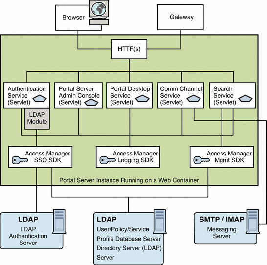
In this figure, the box encloses the Portal Server instance running on Web Server technology. Within the instance are five servlets (Authentication, Portal Server administration console, Portal Desktop, Communication Channel, and Search), and the three SDKs (Access Manager SSO, Access Manager Logging, and Access Manager Management). The Authentication service servlet also makes use of an LDAP service provider module.
A user uses either a browser or the Gateway to communicate with Portal Server. This traffic is directed to the appropriate servlet. Communication occurs between the Authentication service’s LDAP module and the LDAP authentication server; between the Communications channel servlet and the SMTP/IMAP messaging server; between the Access Manager SSO SDK and the LDAP server; and between the Access Manager Management SDK and the LDAP server.
Figure 4–1 shows that if the following processes or communication links fail, the portal solution becomes unavailable to end users:
-
Portal Server Instance. Runs in the context of a web container. Components within an instance communicate through the JVM using JavaTM APIs. An instance is a fully qualified domain name and a TCP port number. Portal Server services are web applications that are implemented as servlets or JSPTM files
Portal Server is built on top of Access Manager for authentication single sign-on (session) management, policy, and profile database access. Thus, Portal Server inherits all the benefits (and constraints) of Access Manager with respect to availability and fault tolerance.
By design, Access Manager’s services are either stateless or the services can share context data. Services can recover to the previous state in case of a service failure.
Within Portal Server, Portal Desktop does not share state data among instances. This means that an instance redirect causes the user context to be rebuilt for the enabled services. Usually, redirected users do not notice this because Portal Server services can rebuild a user context from the user’s profile, and by using contextual data stored in the request. While this statement is generally true for out-of-the-box services, it might not be true for channels or custom code. Developers need to be careful to not design stateful channels to avoid loss of context upon instance failover.
-
Profile Database Server. The profile database server is implemented by Directory Server software. Although this server is not strictly part of Portal Server, availability of the server and integrity of the database are fundamental to the availability of the system.
-
Authentication Server. This is the directory server for LDAP authentication (usually, the same server as the profile database server). You can apply the same high availability techniques to this server as for the profile database server.
-
SRA Gateway and Proxies . The SRA Gateway is a standalone Java technology process that can be considered stateless, because state information can be rebuilt transparently to end users. The Gateway profile maintains a list of Portal Server instances and does round robin load balancing across the Gateway instances. Session stickiness is not required in front of a Gateway, but with session stickiness, performance is better. On the other hand, session stickiness to Portal Server instances is enforced by SRA.
SRA includes other Java technology processes called Netlet Proxy and Rewriter Proxy. You use these proxies to extend the security perimeter from behind the firewall, and limit the number of holes in the DMZ. You can install these proxies on separate nodes.
Example Portal Server Logical Architectures
This section provides some examples of logical architectures for Portal Server:
A Typical Portal Server Installation
Figure 4–2 illustrates some of the components of a portal deployment but does not address the actual physical network design, single points of failure, nor high availability.
This illustration shows the high-level architecture of a typical installation at a company site for a business-to-employee portal. In this figure, the Gateway is hosted in the company’s DMZ along with other systems accessible from the Internet, including proxy/cache servers, web servers, and mail Gateways. The portal node, portal search node, and directory server, are hosted on the internal network where users have access to systems and services ranging from individual employee desktop systems to legacy systems.
Note –
If you are designing an ISP hosting deployment, which hosts separate Portal Server instances for business customers who each want their own portal, contact your Sun representative. Portal Server requires customizations to provide ISP hosting functionality.
Figure 4–2 shows users on the Internet accessing the Gateway from a browser. The Gateway connects the user to the IP address and port for portal users attempting to access. For example, a B2B portal would usually allow access to only port 443, the HTTPS port. Depending on the authorized use, the Gateway forwards requests to the portal node, or directly to the service on the enterprise internal network.
Figure 4–2 High-level Architecture for a Business-to-Employee Portal
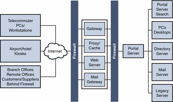
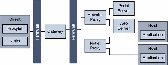
Figure 4–3 shows a Portal Server deployment with SRA services.
Figure 4–3 SRA Deployment
Portal Server Building Modules
Because deploying Portal Server is a complex process involving many other systems, this section describes a specific configuration that provides optimum performance and horizontal scalability. This configuration is known as a Portal Server building module.
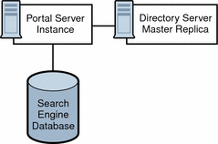
A Portal Server building module is a hardware and software construct with limited or no dependencies on shared services. A typical deployment uses multiple building modules to achieve optimum performance and horizontal scalability. Figure 4–4 shows the building module architecture.
Figure 4–4 Portal Server Building Module Architecture
Note –
The Portal Server building module is simply a recommended configuration. In some cases, a different configuration might result in slightly better throughput (usually at the cost of added complexity). For example, adding another instance of Portal Server to a four CPU system might result in up to ten percent additional throughput, at the cost of requiring a load balancer even when using just a single system.
Building Modules and High Availability Scenarios
Portal Server provides three scenarios for high availability:
-
The system is available as long as the hardware does not fail and as long as the Portal Server processes can be restarted by the watchdog process.
-
The use of hardware and software replication creates a deployment with no single point of failure (NSPOF). The system is always available, as long as no more than one failure occurs consecutively anywhere in the chain of components. However, in the case of failures, user sessions are lost.
-
The system is always available but in addition to NSPOF, failover to a backup instance occurs transparently to end users. In most cases, users do not notice that they have been redirected to a different node or instance. Sessions are preserved across nodes so that users do not have to reauthenticate. Portal Server services are stateless or use checkpointing mechanisms to rebuild the current execution context up to a certain point.
Possible supported architectures include the following:
This section explains implementing these architectures and leverages the building module concept, from a high-availability standpoint.
Table 4–1 summarizes these high availability scenarios along with their supporting techniques.
Table 4–1 Portal Server High Availability Scenarios|
Component Requirements |
Necessary for Best Effort Deployment? |
Necessary for NSPOF Deployment? |
Necessary for Transparent Failover Deployment? |
|---|---|---|---|
|
Yes |
Yes |
Yes |
|
|
Portal Server Building Modules |
No |
Yes |
Yes |
|
No |
Yes |
Yes |
|
|
Load Balancing |
Yes |
Yes |
Yes |
|
No |
No |
Yes |
|
|
No |
No | ||
|
No |
No |
Yes |
Note –
Load balancing is not provided out-of-the-box with the Web Server product.
Best Effort
In this scenario, you install Portal Server and Directory Server on a single node that has a secured hardware configuration for continuous availability, such as Sun Fire UltraSPARCTM III machines. (Securing a SolarisTM Operating Environment system requires that changes be made to its default configuration.)
This type of server features full hardware redundancy, including: redundant power supplies, fans, system controllers; dynamic reconfiguration; CPU hot-plug; online upgrades; and disks rack that can be configured in RAID 0+1 (striping plus mirroring), or RAID 5 using a volume management system, which prevents loss of data in case of a disk crash. Figure 4–5 shows a small, best effort deployment using the building module architecture.
Figure 4–5 Best Effort Scenario
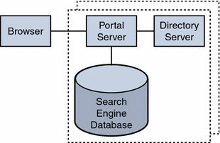
In this scenario, for memory allocation, four CPUs by eight GB RAM (4x8) of memory is sufficient for one building module. The Portal Server console is outside of the building module so that it can be shared with other resources. (Your actual sizing calculations might result in a different allocation amount.)
This scenario might suffice for task critical requirements. Its major weakness is that a maintenance action necessitating a system shutdown results in service interruption.
When SRA is used, and a software crash occurs, a watchdog process automatically restarts the Gateway, Netlet Proxy, and Rewriter Proxy.
No Single Point of Failure
Portal Server natively supports the no single point of failure (NSPOF) scenario. NSPOF is built on top of the best effort scenario, and in addition, introduces replication and load balancing.
Figure 4–6 shows a building module consisting of a a Portal Server instance, a Directory Server replica for profile reads and a search engine database. As such, at least two building modules are necessary to achieve NSPOF, thereby providing a backup if one of the building modules fails. These building modules consist of four CPUs by eight GB RAM.
Figure 4–6 No Single Point of Failure Example
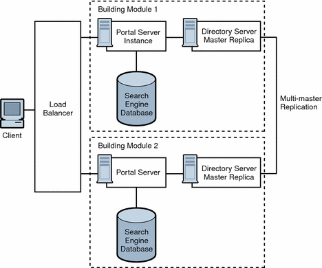
When the load balancer detects Portal Server failures, it redirects users’ requests to a backup building module. Accuracy of failure detection varies among load balancing products. Some products are capable of checking the availability of a system by probing a service involving several functional areas of the server, such as the servlet engine, and the JVM. In particular, most vendor solutions from Resonate, Cisco, Alteon, and others enable you to create arbitrary scripts for server availability. As the load balancer is not part of the Portal Server software, you must acquire it separately from a third-party vendor.
Note –
Access Manager requires that you set up load balancing to enforce sticky sessions. This means that once a session is created on a particular instance, the load balancer needs to always return to the same instance for that session. The load balancer achieves this by binding the session cookie with the instance name identification. In principle, that binding is reestablished when a failed instance is decommissioned. Sticky sessions are also recommended for performance reasons.
Multi-master replication (MMR) takes places between the building modules. The changes that occur on each directory are replicated to the other, which means that each directory plays both roles of supplier and consumer. For more information on MMR, refer to the Sun Java System Directory Server Deployment Guide.
Note –
In general, the Directory Server instance in each building module is configured as a replica of a master directory, which runs elsewhere. However, nothing prevents you from using a master directory as part of the building module. The use of masters on dedicated nodes does not improve the availability of the solution. Use dedicated masters for performance reasons.
Redundancy is equally important to the directory master so that profile changes through the administration console or the Portal Desktop, along with consumer replication across building modules, can always be maintained. Portal Server and Access Manager support MMR. The NSPOF scenario uses a multi-master configuration. In this configuration, two suppliers can accept updates, synchronize with each other, and update all consumers. The consumers can refer update requests to both masters.
SRA follows the same replication and load balancing pattern as Portal Server to achieve NSPOF. As such, two SRA Gateways and pair of proxies are necessary in this scenario. The SRA Gateway detects a Portal Server instance failure when the instance does not respond to a request after a certain time-out value. When this occurs, the HTTPS request is routed to a backup server. The SRA Gateway performs a periodic check for availability until the first Portal Server instance is up again.
The NSPOF high availability scenario is suitable to business critical deployments. However, some high availability limitations in this scenario might not fulfill the requirements of a mission critical deployment.
Transparent Failover
Transparent failover uses the same replication model as the NSPOF scenario but provides additional high availability features, which make the failover to a backup server transparent to end users.
Figure 4–7 shows a transparent failover scenario. Two building modules are shown, consisting of four CPUs by eight GB RAM. Load balancing is responsible for detecting Portal Server failures and redirecting users’ requests to a backup Portal Server in the building module. Building Module 1 stores sessions in the sessions repository. If a crash occurs, the application server retrieves sessions created by Building Module 1 from the sessions repository.
Figure 4–7 Transparent Failover Example Scenario
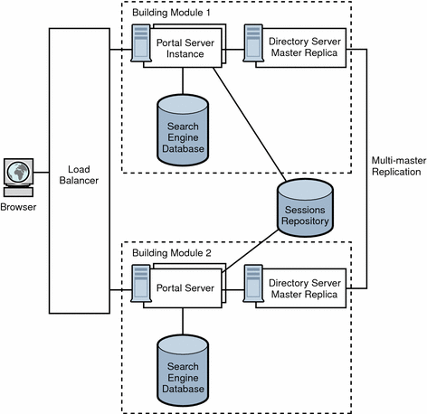
The session repository is provided by the application server software. Portal Server is running in an application server. Portal Server supports transparent failover on application servers that support HttpSession failover. See Chapter 9, Portal Server and Application Servers for more information.
With session failover, users do not need to reauthenticate after a crash. In addition, portal applications can rely on session persistence to store context data used by the checkpointing. You configure session failover in the AMConfig.properties file by setting the com.iplanet.am.session.failover.enabled property to true.
The Netlet Proxy cannot support the transparent failover scenario because of the limitation of the TCP protocol. The Netlet Proxy tunnels TCP connections, and you cannot migrate an open TCP connection to another server. A Netlet Proxy crash drops off all outstanding connections that would have to be reestablished.
Building Module Solution Recommendations
This section describes guidelines for deploying your building module solution.
How you construct your building module affects performance. Consider the following recommendations to deploy your building module properly:
-
Deploy a building module on a single machine.
-
If you use multiple machines, or if your Portal Server machine is running a large number of instances, use a fast network interconnect.
-
On servers with more than eight CPUs, create processor sets or domains with either two or four CPUs. For example, if you choose to install two instances of Portal Server on an eight CPU server, create two four-CPU processor sets.
Directory Server
Identify your Directory Server requirements for your building module deployment. For specific information on Directory Server deployment, see the Directory Server Deployment Guide.
Consider the following Directory Server guidelines when you plan your Portal Server deployment:
-
The amount of needed CPU in the Directory Server consumer replica processor set depends on the number of Portal Server instances in the building module as well as performance and capacity considerations.
-
If possible, dedicate a Directory Server instance for the sole use of the Portal Server instances in a building module.
-
Map the entire directory database indexes and cache in memory to avoid disk latency issues.
-
When deploying multiple building modules, use a multi-master configuration to work around bottlenecks caused by the profile updates and replication overhead to the Directory Server supplier.
LDAP
The scalability of building modules is based on the number of LDAP writes resulting from profile updates and the maximum size of the LDAP database.
Note –
If the LDAP server crashes with the _db files in the /tmp directory, the files are lost when the server restarts. This improves performance but also affects availability.
If the analysis at your specific site indicates that the number of LDAP write operations is indeed a constraint, some of the possible solutions include creating building modules that replicate only a specific branch of the directory and a layer in front that directs incoming requests to the appropriate instance of portal.
Search Engine
When you deploy the Search Engine as part of your building module solution, consider the following:
-
In each building module, make sure only one Portal Server instance has the Search Engine database containing the Resrouce Descriptors (RDs). The remaining Portal Server instances have default empty Search Engine databases.
-
Factors that influence whether to use a building module for the portal Search database include the intensity of search activities in a Portal Server deployment, the range of search hits, and the average number of search hits for all users, in addition to the number of concurrent searches. For example, the load generated on a server by the Search Engine can be both memory and CPU intensive for a large index and heavy query load.
-
You can install Search on a machine separate from Portal Server, to keep the main server dedicated to portal activity. When you do so, you use the searchURL property of the Search provider to point to the second machine where Search is installed. The Search instance is a normal portal instance. You install the Search instance just as you do the portal instance, but use it just for Search functionality.
Access Manager and Portal Server on Separate Nodes
Figure 4–8 illustrates Access Manager and Portal Server residing on separate nodes.
Figure 4–8 Access Manager and Portal Server on Different Nodes
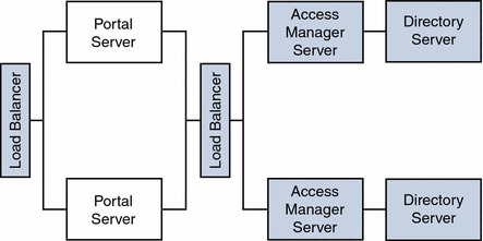
As a result of this implementation of Portal Server and Access Manager separation, other topology permutations are possible for portal services architecture deployments as shown in the next three figures.
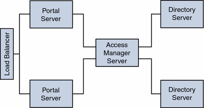
Two Portal Servers One Access Manager
Figure 4–9 shows two Portal Server instances configured to work with a single Access Manager and two Directory Servers where both the Access Manager and the Directory Servers operate in a Java Enterprise System Sun Clustered environment. This configuration is ideal when Access Manager and Directory Server instances are not the bottleneck.
Figure 4–9 Two Portal Servers and One Access Manager
Two Portal Servers Two Access Managers
Figure 4–10 shows a configuration for maximum horizontal scalability and higher availability achieved by a horizontal server farm. Two Portals Servers can be fronted with a load balancer for maximum throughput and high availability.
Another load balancer can be put between Portal Servers and Access Managers to achieve authentication and policy processes as a load distributor and failover mechanism for higher availability.
In this scenario, Blade 1500s can be utilized for Portal Services to distribute the load, similar Blades can be used to host Access Manager Services and Directory Services respectively. With the architecture shown in Figure 4–10, a redundancy of services exists for each of the product stack, therefore, most of the unplanned downtime can be minimized or eliminated.
However, the planned downtime is still an issue. If an upgrade or patch includes changes to the Directory Server software schema used by the Access Manager software, all of the software components must be stopped to update the schema information stored in the Directory Server. However, updating schema information can be considered a fairly rare occurrence in most patch upgrades.
Figure 4–10 Two Portal Servers and Two Access Managers

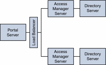
One Load Balancer Two Access Managers
Figure 4–11 shows configuration allowing authentication throughput coming from Portal Server to be load-balanced across the two Access Managers.
This configuration could be implemented when the Portal Server resides on a high-end medium to large server (that is 1 to 4 processors) with a very wide bandwidth network connection. The Access Managers with the policy and authentication services could be on two medium-size servers.
Figure 4–11 Load Balancing two Access Managers
Example SRA Logical Architectures
The SRA Gateway provides the interface and security barrier between the remote user sessions originating from the Internet and your organization’s intranet. The Gateway serves two main functions:
-
Provides basic authentication services to incoming user sessions, including establishing identity and allowing or denying access to the platform.
-
Provides mapping and rewriting services to enable web-based links to the intranet content for users.
For Internet access, use 128-bit SSL to provide the best security arrangement and encryption or communication between the user’s browser and Portal Server. The Gateway, Netlet, NetFile, Netlet Proxy, Rewriter Proxy, and Proxylet constitute the major components of SRA.
This section lists some of the possible configurations of these components. This section is meant only as a guide, not a complete deployment reference. Choose a configuration based on your business needs:
Tip –
To set up the authlessanonymous page to display through the Gateway, add /portal/dt to the non-authenticated URLs of the gateway profile. However, this means that even for normal users, portal pages will not need authentication and no session validation is performed.
Basic SRA Configuration
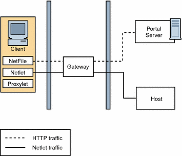
Figure 4–12 shows the most simple configuration possible for SRA. The figure shows a client browser running NetFile and Netlet. The Gateway is installed on a separate machine in the DMZ between two firewalls. The Portal Server is located on a machine beyond the second firewall in the intranet. The other application hosts that the client accesses are also located beyond the second firewall in the intranet.
The Gateway is in the DMZ with the external port open in the firewall through which the client browser communicates with the Gateway. In the second firewall, for HTTP or HTTPS traffic, the Gateway can communicate directly with internal hosts. If security policies do not permit it, use SRA proxies between the Gateway and the internal hosts. For Netlet traffic, the connection is direct from the Gateway to the destination host.
Without a SRA proxy, the SSL traffic is limited to the Gateway and the traffic is unencrypted from the Gateway to the internal host (unless the internal host is running in HTTPS mode). Any internal host to which the Gateway has to initiate a Netlet connection should be directly accessible from DMZ. This can be a potential security problem and hence this configuration is recommended only for the simplest of installations.
Figure 4–12 Basic SRA Configuration
Disable Netlet
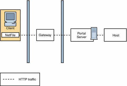
Figure 4–13 shows a scenario similar to the basic SRA configuration except that Netlet is disabled. If the client deployment is not going to use Netlet for securely running applications that need to communicate with intranet, then use this setup for performance improvement.
You can extend this configuration and combine it with other deployment scenarios to provide better performance and a scalable solution.
Figure 4–13 Disable Netlet
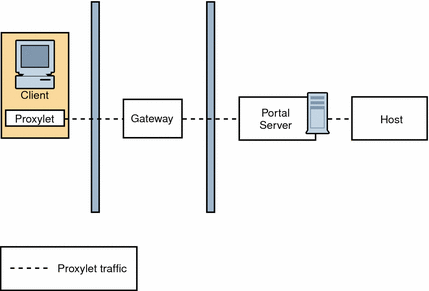
Proxylet
Figure 4–14 illustrates how Proxylet enables users to securely access intranet resources through the Internet without exposing these resources to the client.
It inherits the transport mode (either HTTP or HTTPS) from the Gateway.
Figure 4–14 Proxylet
Multiple Gateway Instances
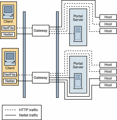
Figure 4–15 shows an extension of the SRA basic configuration. Multiple Gateway instances run on the same machine or multiple machines. You can start multiple Gateway instances with different profiles.
Figure 4–15 Multiple Gateway Instances
Note –
Although Figure 4–15 shows a 1-to-1 correspondence between the Gateway and the Portal Servers, this need not necessarily be the case in a real deployment. You can have multiple Gateway instances, and multiple Portal Server instances, and any Gateway can contact any Portal Server depending on the configuration.
The disadvantage to this configuration is that multiple ports need to be opened in the second firewall for each connection request. This could cause potential security problems.
Netlet and Rewriter Proxies
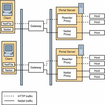
Figure 4–16 shows a configuration with a Netlet Proxy and a Rewriter Proxy. With these proxies, only two open ports are necessary in the second firewall.
The Gateway need not contact the application hosts directly now, but will forward all Netlet traffic to the Netlet proxy and Rewriter traffic to the Rewriter Proxy. Since the Netlet Proxy is within the intranet, it can directly contact all the required application hosts without opening multiple ports in the second firewall.
The traffic between the Gateway in the DMZ and the Netlet Proxy is encrypted, and gets decrypted only at the Netlet Proxy, thereby enhancing security.
If the Rewriter Proxy is enabled, all traffic is directed through the Rewriter Proxy, irrespective of whether the request is for the Portal Server node or not. This ensures that the traffic from the Gateway in the DMZ to the intranet is always encrypted.
Because the Netlet Proxy, Rewriter Proxy, and Portal Server are all running on the same node, there might be performance issues in such a deployment scenario. This problem is overcome when proxies are installed on a separate nodes to reduce the load on the Portal Server node.
Figure 4–16 Netlet and Rewriter Proxies
Netlet and Rewriter Proxies on Separate Nodes
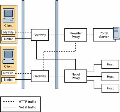
To reduce the load on the Portal Server node and still provide the same level of security at increased performance, you can install Netlet and Rewriter Proxies on separate nodes. This deployment has an added advantage in that you can use a proxy and shield the Portal Server from the DMZ. The node that runs these proxies needs to be directly accessible from the DMZ.
Figure 4–17 shows the Netlet Proxy and Rewriter Proxy on separate nodes. Traffic from the Gateway is directed to the separate node, which in turn directs the traffic through the proxies and to the required intranet hosts.
You can have multiple instances or installations of Netlet and Rewriter Proxies. You can configure each Gateway to try to contact various instances of the proxies in a round robin manner depending on availability.
Figure 4–17 Proxies on Separate Nodes
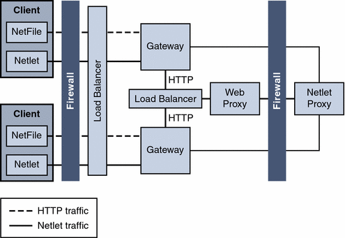
Two Gateways and Netlet Proxy
Load balancers provide a failover mechanism for higher availability for redundancy of services on the Portal Servers and Access Managers.
Figure 4–18 Two Gateways and Netlet Proxy
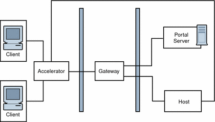
Gateway with Accelerator
You can configure an external SSL device to run in front of the Gateway in open mode. It provides the SSL link between the client and SRA. For information on accelerators, see the Sun Java System Portal Server 6 Secure Remote Access 2005Q4 Administration Guide
Figure 4–19 SRA Gateway with External Accelerator
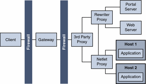
Netlet with 3rd Party Proxy
Netlet with 3rd Party Proxy illustrates using a third-party proxy to limit the number of ports in the second firewall to one. You can configure the Gateway to use a third-party proxy to reach the Rewriter and the Netlet Proxies.
Figure 4–20 Netlet and Third-Party Proxy
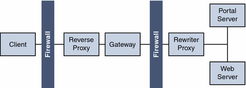
Reverse Proxy
A proxy server serves Internet content to the intranet, while a reverse proxy serves intranet content to the Internet. Certain deployments of reverse proxy are configured to serve the Internet content to achieve load balancing and caching.
Figure 4–21 illustrates how you can configure a reverse proxy in front of the Gateway to serve both Internet and intranet content to authorized users. Whenever the Gateway serves web content, it needs to ensure that all subsequent browser requests based on this content are routed through the Gateway. This is achieved by identifying all URLs in this content and rewriting as appropriate.
Figure 4–21 Using a Reverse Proxy in Front of the Gateway
Deployment Scenario
The completed logical architecture design by itself is not sufficient to move forward to the deployment design phase of the solution life cycle. You need to pair the logical architecture with the quality of service (QoS) requirements determined during the technical requirements phase. The pairing of the logical architecture with the QoS requirements constitutes a deployment scenario. The deployment scenario is the starting point for designing the deployment architecture, as explained in Chapter 5, Deployment Design.
- © 2010, Oracle Corporation and/or its affiliates
