Example Portal Server Logical Architectures
This section provides some examples of logical architectures for Portal Server:
A Typical Portal Server Installation
Figure 4–2 illustrates some of the components of a portal deployment but does not address the actual physical network design, single points of failure, nor high availability.
This illustration shows the high-level architecture of a typical installation at a company site for a business-to-employee portal. In this figure, the Gateway is hosted in the company’s DMZ along with other systems accessible from the Internet, including proxy/cache servers, web servers, and mail Gateways. The portal node, portal search node, and directory server, are hosted on the internal network where users have access to systems and services ranging from individual employee desktop systems to legacy systems.
Note –
If you are designing an ISP hosting deployment, which hosts separate Portal Server instances for business customers who each want their own portal, contact your Sun representative. Portal Server requires customizations to provide ISP hosting functionality.
Figure 4–2 shows users on the Internet accessing the Gateway from a browser. The Gateway connects the user to the IP address and port for portal users attempting to access. For example, a B2B portal would usually allow access to only port 443, the HTTPS port. Depending on the authorized use, the Gateway forwards requests to the portal node, or directly to the service on the enterprise internal network.
Figure 4–2 High-level Architecture for a Business-to-Employee Portal
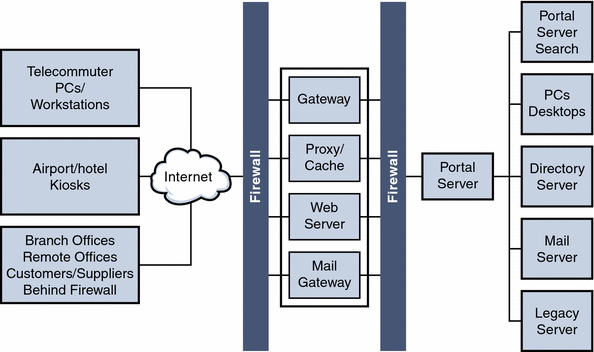
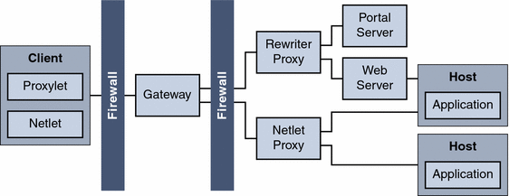
Figure 4–3 shows a Portal Server deployment with SRA services.
Figure 4–3 SRA Deployment
Portal Server Building Modules
Because deploying Portal Server is a complex process involving many other systems, this section describes a specific configuration that provides optimum performance and horizontal scalability. This configuration is known as a Portal Server building module.
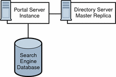
A Portal Server building module is a hardware and software construct with limited or no dependencies on shared services. A typical deployment uses multiple building modules to achieve optimum performance and horizontal scalability. Figure 4–4 shows the building module architecture.
Figure 4–4 Portal Server Building Module Architecture
Note –
The Portal Server building module is simply a recommended configuration. In some cases, a different configuration might result in slightly better throughput (usually at the cost of added complexity). For example, adding another instance of Portal Server to a four CPU system might result in up to ten percent additional throughput, at the cost of requiring a load balancer even when using just a single system.
Building Modules and High Availability Scenarios
Portal Server provides three scenarios for high availability:
-
The system is available as long as the hardware does not fail and as long as the Portal Server processes can be restarted by the watchdog process.
-
The use of hardware and software replication creates a deployment with no single point of failure (NSPOF). The system is always available, as long as no more than one failure occurs consecutively anywhere in the chain of components. However, in the case of failures, user sessions are lost.
-
The system is always available but in addition to NSPOF, failover to a backup instance occurs transparently to end users. In most cases, users do not notice that they have been redirected to a different node or instance. Sessions are preserved across nodes so that users do not have to reauthenticate. Portal Server services are stateless or use checkpointing mechanisms to rebuild the current execution context up to a certain point.
Possible supported architectures include the following:
This section explains implementing these architectures and leverages the building module concept, from a high-availability standpoint.
Table 4–1 summarizes these high availability scenarios along with their supporting techniques.
Table 4–1 Portal Server High Availability Scenarios|
Component Requirements |
Necessary for Best Effort Deployment? |
Necessary for NSPOF Deployment? |
Necessary for Transparent Failover Deployment? |
|---|---|---|---|
|
Yes |
Yes |
Yes |
|
|
Portal Server Building Modules |
No |
Yes |
Yes |
|
No |
Yes |
Yes |
|
|
Load Balancing |
Yes |
Yes |
Yes |
|
No |
No |
Yes |
|
|
No |
No | ||
|
No |
No |
Yes |
Note –
Load balancing is not provided out-of-the-box with the Web Server product.
Best Effort
In this scenario, you install Portal Server and Directory Server on a single node that has a secured hardware configuration for continuous availability, such as Sun Fire UltraSPARCTM III machines. (Securing a SolarisTM Operating Environment system requires that changes be made to its default configuration.)
This type of server features full hardware redundancy, including: redundant power supplies, fans, system controllers; dynamic reconfiguration; CPU hot-plug; online upgrades; and disks rack that can be configured in RAID 0+1 (striping plus mirroring), or RAID 5 using a volume management system, which prevents loss of data in case of a disk crash. Figure 4–5 shows a small, best effort deployment using the building module architecture.
Figure 4–5 Best Effort Scenario
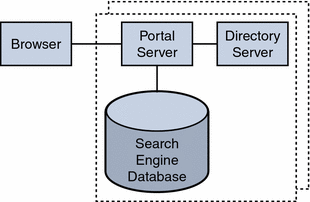
In this scenario, for memory allocation, four CPUs by eight GB RAM (4x8) of memory is sufficient for one building module. The Portal Server console is outside of the building module so that it can be shared with other resources. (Your actual sizing calculations might result in a different allocation amount.)
This scenario might suffice for task critical requirements. Its major weakness is that a maintenance action necessitating a system shutdown results in service interruption.
When SRA is used, and a software crash occurs, a watchdog process automatically restarts the Gateway, Netlet Proxy, and Rewriter Proxy.
No Single Point of Failure
Portal Server natively supports the no single point of failure (NSPOF) scenario. NSPOF is built on top of the best effort scenario, and in addition, introduces replication and load balancing.
Figure 4–6 shows a building module consisting of a a Portal Server instance, a Directory Server replica for profile reads and a search engine database. As such, at least two building modules are necessary to achieve NSPOF, thereby providing a backup if one of the building modules fails. These building modules consist of four CPUs by eight GB RAM.
Figure 4–6 No Single Point of Failure Example
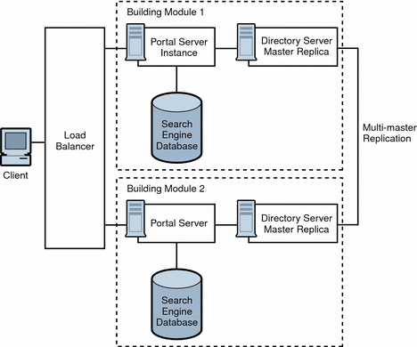
When the load balancer detects Portal Server failures, it redirects users’ requests to a backup building module. Accuracy of failure detection varies among load balancing products. Some products are capable of checking the availability of a system by probing a service involving several functional areas of the server, such as the servlet engine, and the JVM. In particular, most vendor solutions from Resonate, Cisco, Alteon, and others enable you to create arbitrary scripts for server availability. As the load balancer is not part of the Portal Server software, you must acquire it separately from a third-party vendor.
Note –
Access Manager requires that you set up load balancing to enforce sticky sessions. This means that once a session is created on a particular instance, the load balancer needs to always return to the same instance for that session. The load balancer achieves this by binding the session cookie with the instance name identification. In principle, that binding is reestablished when a failed instance is decommissioned. Sticky sessions are also recommended for performance reasons.
Multi-master replication (MMR) takes places between the building modules. The changes that occur on each directory are replicated to the other, which means that each directory plays both roles of supplier and consumer. For more information on MMR, refer to the Sun Java System Directory Server Deployment Guide.
Note –
In general, the Directory Server instance in each building module is configured as a replica of a master directory, which runs elsewhere. However, nothing prevents you from using a master directory as part of the building module. The use of masters on dedicated nodes does not improve the availability of the solution. Use dedicated masters for performance reasons.
Redundancy is equally important to the directory master so that profile changes through the administration console or the Portal Desktop, along with consumer replication across building modules, can always be maintained. Portal Server and Access Manager support MMR. The NSPOF scenario uses a multi-master configuration. In this configuration, two suppliers can accept updates, synchronize with each other, and update all consumers. The consumers can refer update requests to both masters.
SRA follows the same replication and load balancing pattern as Portal Server to achieve NSPOF. As such, two SRA Gateways and pair of proxies are necessary in this scenario. The SRA Gateway detects a Portal Server instance failure when the instance does not respond to a request after a certain time-out value. When this occurs, the HTTPS request is routed to a backup server. The SRA Gateway performs a periodic check for availability until the first Portal Server instance is up again.
The NSPOF high availability scenario is suitable to business critical deployments. However, some high availability limitations in this scenario might not fulfill the requirements of a mission critical deployment.
Transparent Failover
Transparent failover uses the same replication model as the NSPOF scenario but provides additional high availability features, which make the failover to a backup server transparent to end users.
Figure 4–7 shows a transparent failover scenario. Two building modules are shown, consisting of four CPUs by eight GB RAM. Load balancing is responsible for detecting Portal Server failures and redirecting users’ requests to a backup Portal Server in the building module. Building Module 1 stores sessions in the sessions repository. If a crash occurs, the application server retrieves sessions created by Building Module 1 from the sessions repository.
Figure 4–7 Transparent Failover Example Scenario
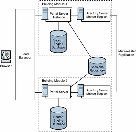
The session repository is provided by the application server software. Portal Server is running in an application server. Portal Server supports transparent failover on application servers that support HttpSession failover. See Chapter 9, Portal Server and Application Servers for more information.
With session failover, users do not need to reauthenticate after a crash. In addition, portal applications can rely on session persistence to store context data used by the checkpointing. You configure session failover in the AMConfig.properties file by setting the com.iplanet.am.session.failover.enabled property to true.
The Netlet Proxy cannot support the transparent failover scenario because of the limitation of the TCP protocol. The Netlet Proxy tunnels TCP connections, and you cannot migrate an open TCP connection to another server. A Netlet Proxy crash drops off all outstanding connections that would have to be reestablished.
Building Module Solution Recommendations
This section describes guidelines for deploying your building module solution.
How you construct your building module affects performance. Consider the following recommendations to deploy your building module properly:
-
Deploy a building module on a single machine.
-
If you use multiple machines, or if your Portal Server machine is running a large number of instances, use a fast network interconnect.
-
On servers with more than eight CPUs, create processor sets or domains with either two or four CPUs. For example, if you choose to install two instances of Portal Server on an eight CPU server, create two four-CPU processor sets.
Directory Server
Identify your Directory Server requirements for your building module deployment. For specific information on Directory Server deployment, see the Directory Server Deployment Guide.
Consider the following Directory Server guidelines when you plan your Portal Server deployment:
-
The amount of needed CPU in the Directory Server consumer replica processor set depends on the number of Portal Server instances in the building module as well as performance and capacity considerations.
-
If possible, dedicate a Directory Server instance for the sole use of the Portal Server instances in a building module.
-
Map the entire directory database indexes and cache in memory to avoid disk latency issues.
-
When deploying multiple building modules, use a multi-master configuration to work around bottlenecks caused by the profile updates and replication overhead to the Directory Server supplier.
LDAP
The scalability of building modules is based on the number of LDAP writes resulting from profile updates and the maximum size of the LDAP database.
Note –
If the LDAP server crashes with the _db files in the /tmp directory, the files are lost when the server restarts. This improves performance but also affects availability.
If the analysis at your specific site indicates that the number of LDAP write operations is indeed a constraint, some of the possible solutions include creating building modules that replicate only a specific branch of the directory and a layer in front that directs incoming requests to the appropriate instance of portal.
Search Engine
When you deploy the Search Engine as part of your building module solution, consider the following:
-
In each building module, make sure only one Portal Server instance has the Search Engine database containing the Resrouce Descriptors (RDs). The remaining Portal Server instances have default empty Search Engine databases.
-
Factors that influence whether to use a building module for the portal Search database include the intensity of search activities in a Portal Server deployment, the range of search hits, and the average number of search hits for all users, in addition to the number of concurrent searches. For example, the load generated on a server by the Search Engine can be both memory and CPU intensive for a large index and heavy query load.
-
You can install Search on a machine separate from Portal Server, to keep the main server dedicated to portal activity. When you do so, you use the searchURL property of the Search provider to point to the second machine where Search is installed. The Search instance is a normal portal instance. You install the Search instance just as you do the portal instance, but use it just for Search functionality.
Access Manager and Portal Server on Separate Nodes
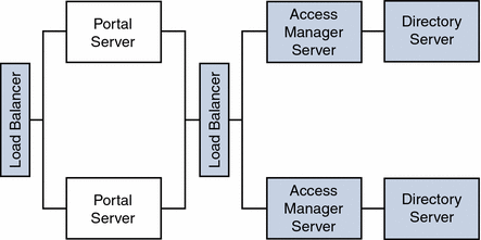
Figure 4–8 illustrates Access Manager and Portal Server residing on separate nodes.
Figure 4–8 Access Manager and Portal Server on Different Nodes
As a result of this implementation of Portal Server and Access Manager separation, other topology permutations are possible for portal services architecture deployments as shown in the next three figures.
Two Portal Servers One Access Manager
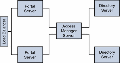
Figure 4–9 shows two Portal Server instances configured to work with a single Access Manager and two Directory Servers where both the Access Manager and the Directory Servers operate in a Java Enterprise System Sun Clustered environment. This configuration is ideal when Access Manager and Directory Server instances are not the bottleneck.
Figure 4–9 Two Portal Servers and One Access Manager
Two Portal Servers Two Access Managers
Figure 4–10 shows a configuration for maximum horizontal scalability and higher availability achieved by a horizontal server farm. Two Portals Servers can be fronted with a load balancer for maximum throughput and high availability.
Another load balancer can be put between Portal Servers and Access Managers to achieve authentication and policy processes as a load distributor and failover mechanism for higher availability.
In this scenario, Blade 1500s can be utilized for Portal Services to distribute the load, similar Blades can be used to host Access Manager Services and Directory Services respectively. With the architecture shown in Figure 4–10, a redundancy of services exists for each of the product stack, therefore, most of the unplanned downtime can be minimized or eliminated.
However, the planned downtime is still an issue. If an upgrade or patch includes changes to the Directory Server software schema used by the Access Manager software, all of the software components must be stopped to update the schema information stored in the Directory Server. However, updating schema information can be considered a fairly rare occurrence in most patch upgrades.
Figure 4–10 Two Portal Servers and Two Access Managers

One Load Balancer Two Access Managers
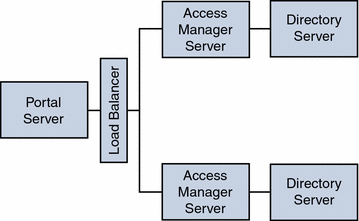
Figure 4–11 shows configuration allowing authentication throughput coming from Portal Server to be load-balanced across the two Access Managers.
This configuration could be implemented when the Portal Server resides on a high-end medium to large server (that is 1 to 4 processors) with a very wide bandwidth network connection. The Access Managers with the policy and authentication services could be on two medium-size servers.
Figure 4–11 Load Balancing two Access Managers
- © 2010, Oracle Corporation and/or its affiliates
