Example SRA Logical Architectures
The SRA Gateway provides the interface and security barrier between the remote user sessions originating from the Internet and your organization’s intranet. The Gateway serves two main functions:
-
Provides basic authentication services to incoming user sessions, including establishing identity and allowing or denying access to the platform.
-
Provides mapping and rewriting services to enable web-based links to the intranet content for users.
For Internet access, use 128-bit SSL to provide the best security arrangement and encryption or communication between the user’s browser and Portal Server. The Gateway, Netlet, NetFile, Netlet Proxy, Rewriter Proxy, and Proxylet constitute the major components of SRA.
This section lists some of the possible configurations of these components. This section is meant only as a guide, not a complete deployment reference. Choose a configuration based on your business needs:
Tip –
To set up the authlessanonymous page to display through the Gateway, add /portal/dt to the non-authenticated URLs of the gateway profile. However, this means that even for normal users, portal pages will not need authentication and no session validation is performed.
Basic SRA Configuration
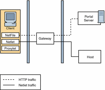
Figure 4–12 shows the most simple configuration possible for SRA. The figure shows a client browser running NetFile and Netlet. The Gateway is installed on a separate machine in the DMZ between two firewalls. The Portal Server is located on a machine beyond the second firewall in the intranet. The other application hosts that the client accesses are also located beyond the second firewall in the intranet.
The Gateway is in the DMZ with the external port open in the firewall through which the client browser communicates with the Gateway. In the second firewall, for HTTP or HTTPS traffic, the Gateway can communicate directly with internal hosts. If security policies do not permit it, use SRA proxies between the Gateway and the internal hosts. For Netlet traffic, the connection is direct from the Gateway to the destination host.
Without a SRA proxy, the SSL traffic is limited to the Gateway and the traffic is unencrypted from the Gateway to the internal host (unless the internal host is running in HTTPS mode). Any internal host to which the Gateway has to initiate a Netlet connection should be directly accessible from DMZ. This can be a potential security problem and hence this configuration is recommended only for the simplest of installations.
Figure 4–12 Basic SRA Configuration
Disable Netlet
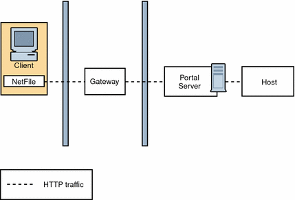
Figure 4–13 shows a scenario similar to the basic SRA configuration except that Netlet is disabled. If the client deployment is not going to use Netlet for securely running applications that need to communicate with intranet, then use this setup for performance improvement.
You can extend this configuration and combine it with other deployment scenarios to provide better performance and a scalable solution.
Figure 4–13 Disable Netlet
Proxylet
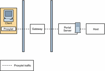
Figure 4–14 illustrates how Proxylet enables users to securely access intranet resources through the Internet without exposing these resources to the client.
It inherits the transport mode (either HTTP or HTTPS) from the Gateway.
Figure 4–14 Proxylet
Multiple Gateway Instances
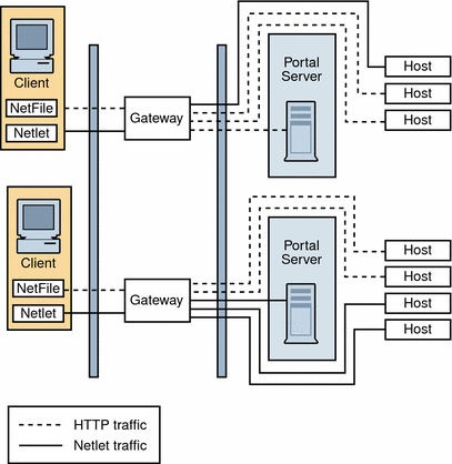
Figure 4–15 shows an extension of the SRA basic configuration. Multiple Gateway instances run on the same machine or multiple machines. You can start multiple Gateway instances with different profiles.
Figure 4–15 Multiple Gateway Instances
Note –
Although Figure 4–15 shows a 1-to-1 correspondence between the Gateway and the Portal Servers, this need not necessarily be the case in a real deployment. You can have multiple Gateway instances, and multiple Portal Server instances, and any Gateway can contact any Portal Server depending on the configuration.
The disadvantage to this configuration is that multiple ports need to be opened in the second firewall for each connection request. This could cause potential security problems.
Netlet and Rewriter Proxies
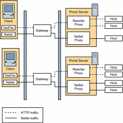
Figure 4–16 shows a configuration with a Netlet Proxy and a Rewriter Proxy. With these proxies, only two open ports are necessary in the second firewall.
The Gateway need not contact the application hosts directly now, but will forward all Netlet traffic to the Netlet proxy and Rewriter traffic to the Rewriter Proxy. Since the Netlet Proxy is within the intranet, it can directly contact all the required application hosts without opening multiple ports in the second firewall.
The traffic between the Gateway in the DMZ and the Netlet Proxy is encrypted, and gets decrypted only at the Netlet Proxy, thereby enhancing security.
If the Rewriter Proxy is enabled, all traffic is directed through the Rewriter Proxy, irrespective of whether the request is for the Portal Server node or not. This ensures that the traffic from the Gateway in the DMZ to the intranet is always encrypted.
Because the Netlet Proxy, Rewriter Proxy, and Portal Server are all running on the same node, there might be performance issues in such a deployment scenario. This problem is overcome when proxies are installed on a separate nodes to reduce the load on the Portal Server node.
Figure 4–16 Netlet and Rewriter Proxies
Netlet and Rewriter Proxies on Separate Nodes
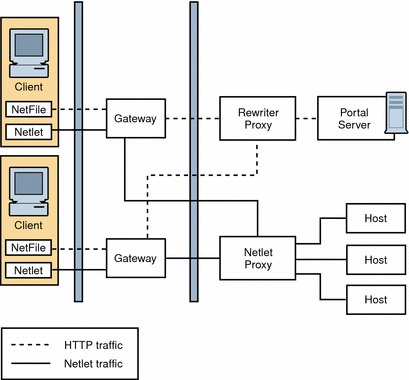
To reduce the load on the Portal Server node and still provide the same level of security at increased performance, you can install Netlet and Rewriter Proxies on separate nodes. This deployment has an added advantage in that you can use a proxy and shield the Portal Server from the DMZ. The node that runs these proxies needs to be directly accessible from the DMZ.
Figure 4–17 shows the Netlet Proxy and Rewriter Proxy on separate nodes. Traffic from the Gateway is directed to the separate node, which in turn directs the traffic through the proxies and to the required intranet hosts.
You can have multiple instances or installations of Netlet and Rewriter Proxies. You can configure each Gateway to try to contact various instances of the proxies in a round robin manner depending on availability.
Figure 4–17 Proxies on Separate Nodes
Two Gateways and Netlet Proxy
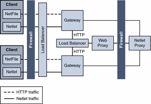
Load balancers provide a failover mechanism for higher availability for redundancy of services on the Portal Servers and Access Managers.
Figure 4–18 Two Gateways and Netlet Proxy
Gateway with Accelerator
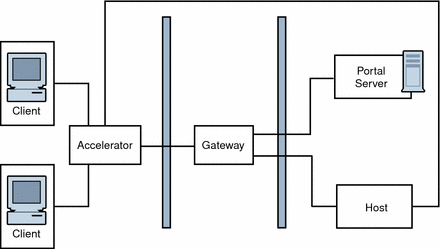
You can configure an external SSL device to run in front of the Gateway in open mode. It provides the SSL link between the client and SRA. For information on accelerators, see the Sun Java System Portal Server 6 Secure Remote Access 2005Q4 Administration Guide
Figure 4–19 SRA Gateway with External Accelerator
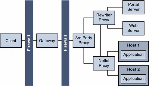
Netlet with 3rd Party Proxy
Netlet with 3rd Party Proxy illustrates using a third-party proxy to limit the number of ports in the second firewall to one. You can configure the Gateway to use a third-party proxy to reach the Rewriter and the Netlet Proxies.
Figure 4–20 Netlet and Third-Party Proxy
Reverse Proxy
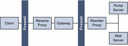
A proxy server serves Internet content to the intranet, while a reverse proxy serves intranet content to the Internet. Certain deployments of reverse proxy are configured to serve the Internet content to achieve load balancing and caching.
Figure 4–21 illustrates how you can configure a reverse proxy in front of the Gateway to serve both Internet and intranet content to authorized users. Whenever the Gateway serves web content, it needs to ensure that all subsequent browser requests based on this content are routed through the Gateway. This is achieved by identifying all URLs in this content and rewriting as appropriate.
Figure 4–21 Using a Reverse Proxy in Front of the Gateway
- © 2010, Oracle Corporation and/or its affiliates
