Recovering From a Power Failure During the Flash PROM Update
If the power was lost during the flash PROM update, complete the power interruption recovery procedure for your system.
Sun Ultra 1 and Ultra 2 Systems, Sun Enterprise 450 System, Sun Ultra 450 Workstation
If power to your system was interrupted during updating of the flash PROM, complete the following steps:
-
Turn the power switch to the Standby position to prevent power surge to the system when power is restored.
-
After power is restored to the system location, return the power switch to the On position.
After power is restored, one of the following two recovery scenarios should happen on your system. Follow the instructions described for the appropriate scenario.
Scenario 1--System Recovers After Power Restoration
If your system attempts to autoboot after power is restored, you must complete the flash PROM updating process. Complete the section "Running the Flash PROM Update Script Manually".
Scenario 2--System Does Not Recover After Power Restoration
If your system does not boot, run diagnostics, or return to the PROM monitor's ok prompt after power is restored, complete the following steps:
-
If the update was being run via a serial port and the system also has a frame buffer and keyboard installed, or if the system has a keyboard and more than one frame buffer installed:
-
Connect a monitor to each frame buffer.
-
Confirm that output has been redirected to one of the frame buffers.
-
The NVRAM configuration variables might have been modified because of the firmware update just before power was lost. If this happened, then the system output was possibly redirected to a device other than the one originally used to display it. This could only have happened if a keyboard was connected to the system.
-
If there is no keyboard connected to the system and the NVRAM configuration variables are set to their default values, then system input and output are directed to serial port A.
-
-
-
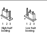
If output cannot be found on any of the installed frame buffers or serial port A, set the boot control jumper to boot from the half of the PROM that is not currently selected. See Figure 4-1 Figure 4-2, Figure 4-3, Figure 4-7, and Figure 4-8. An asterisk (*) on the main logic board notes the location of pin 1.
-
If the jumper is set for high-half booting, move it to low-half booting (pins 2 and 3 jumpered). See Figure 4-7.
-
If the jumper is set for low-half booting, move it to high-half booting (pins 1 and 2 jumpered). See Figure 4-7.
System
Jumper
Pins 1 + 2 Jumpered
Pins 2 + 3 Jumpered
Default Jumper on Pins
Name
Ultra 1, 2
J2204
High-half booting
Low-half booting
2 + 3
Boot control
Sun Enterprise 450 or Sun Ultra 450 workstation
J5501
High-half booting
Low-half booting
2 + 3
Boot control
Figure 4-7 Setting the Boot Control Jumper to Low-Half Booting or High-Half Booting

-
-
Power on the system unit.
-
If the system recovers, complete the programming process by rebooting. Complete the steps in the section "Running the Flash PROM Update Script Manually".
-
If the system does not recover, repeat Step 1 and Step 2 a second time.
-
-
If the system still does not recover, contact your Sun service provider or local Sun service Authorized Service Provider.
- © 2010, Oracle Corporation and/or its affiliates
