| Sun Blade X6270 Server Module Service Manual |
| C H A P T E R 3 |
|
Maintaining the Sun Blade X6270 Server |
This chapter contains information and procedures for servicing the Sun Blade X6270 Server Module hardware.
This chapter contains the following topics:
You can service the server with the following items:
Internal modules and options are electronic components that are extremely sensitive to static electricity. Ordinary amounts of static from your clothes or work environment can destroy components.
To prevent static damage whenever you are accessing any of the internal components, you must:
Each server module arrives with module-replacement filler panels for CPUs, storage drives, and memory modules. These filler panels are installed at the factory and must remain in the server until you are ready to replace them with a purchased module.
A filler panel is a metal or plastic enclosure that does not contain any functioning system hardware or cable connectors. These panels must remain in any unused module slots (storage drives, DIMMs, servers, and CPUs) to ensure proper airflow throughout the system. If you remove a filler panel and continue to operate your system with an empty module slot, the operating performance for your system could decline.
TABLE 3-1 identifies how to remove or insert server module replacement filler panels
| Note - For instructions for adding or replacing chassis component filler panels (for example: network modules or chassis monitoring modules), consult the documentation supplied with your chassis. |
Use the preparatory procedures in this section when you are referred to them from the removal and replacement procedures.

|
Caution - Do not operate the system with empty slots. Always insert a filler panel into an empty slot to reduce the possibility of system shut down. |
To replace components for the Sun Blade X6270 Server Module, with the exception of the hard disk drives, you need to remove the server module from the chassis.
| Note - If you are only replacing the hard disk drives in the server, you can skip this section and go to Replacing or Adding a Hard Disk Drive. |
1. Power off the server and verify that the server is ready to be removed from chassis.
For instructions, see Power Off and Verify Server Is Ready for Removal From Chassis.
2. Perform the following steps to remove the server from the chassis.
See FIGURE 3-1.
a. To open the ejector levers on the server: 1) press the green ejector button at the top and bottom to unlatch the server from chassis; then 2) swing out the top and bottom levers.
b. To slide the server from the chassis: 1) hold the opened ejector levers and pull the ejector levers toward you; then 2) grasp the server with both hands and slide it toward you away from the chassis.
FIGURE 3-1 Removing the Server From the Chassis

3. Place the server on a flat antistatic surface.
4. Install a server module filler panel in the unused server slot to ensure proper airflow throughout the system.

|
Caution - If you operate the chassis with an empty server module slot, it is possible that you will notice a reduction in the performance of your system. |
Refer to the following instructions for removing or installing the cover on the server.
|
1. Press down on the cover release button and, using the indent for leverage, slide the main cover toward the rear of the chassis approximately 0.5 inch (12 mm).
See FIGURE 3-2.
FIGURE 3-2 Removing the Main Cover

2. Grasp the cover by its rear edge and lift it straight up from the chassis.
|
1. Slide the cover under the tabs at the front of the server module.
2. Gently press down on the cover to engage it with the chassis.
3. When applicable, install the server in the chassis and power on the system.
For instructions, see the Sun Blade X6270 Server Module Installation Guide.
FIGURE 3-3 shows the locations of the replaceable Sun Blade X6270 Server Module components that are documented in this chapter.
FIGURE 3-3 Sun Blade X6270 Server Module Replaceable Component Locations

|
The DIMMs are shown populated in DIMM slots 2, 5, 8 for each CPU. Processor chip contains memory controller. Do not attempt to populate DIMMs sockets next to unpopulated (empty) CPU sockets. |
|
|
DIMM filler panels shown populated in DIMM slots 0, 1, 3, 4, 6 & 7. The DIMM filler panels should remain in unpopulated DIMM slots until the DIMM filler panel can be replaced with a DIMM. Otherwise, you may experience a reduction in system performance. |
|
|
CPU heatsinks (up to two CPUs may be installed) The minimum CPU configuration shipped includes one CPU with a heatsink. An air baffle is shipped to cover the empty CPU socket (not shown in FIGURE 3-3). Additional CPUs may be ordered. In the example shown in FIGURE 3-3, the CPUs are installed under the two heatsinks. |
|
|
Storage devices (hard disk drives (HDD) or solid state drives (SSD) Up to four hard disk drives or solid state drives may be populated. |
| Note - Supported components and their part numbers are subject to change over time. For the most up-to-date list of replaceable components for the Sun Blade X6270 Server Module, click on the X6270 Server Module product page at: http://sunsolve.sun.com/handbook_pub/Systems/ |
This section contains procedures for replacing the following components:
When replacing or adding a hard disk drive on the Sun Blade X6270 Server Module refer to following sections:
| Note - This component is a hot-swappable CRU and can be replaced by anyone. |
The internal system software designation for storage devices (hard disk drives (HDD) or solid state drives (SSD) is shown in FIGURE 3-4.
FIGURE 3-4 Designation of HDDs or SSD

A single storage device failure does not cause a data failure if the storage devices are configured as a mirrored RAID 1 volume (optional). The storage device can be removed, and when a new storage device is inserted, the contents are automatically rebuilt from the rest of the array with no need to reconfigure the RAID parameters. If the replaced storage drive was configured as a hot-spare, the new HDD is automatically configured as a new hot-spare.
For information about the implementation of RAID on this server and references to RAID controller documentation, refer to the Sun Disk Management Overview For X64 Sun Fire and Sun Blade Series Servers (820-6350).
Use the following procedure to replace a HDD or SSD.
1. Observe the LEDs on the front panel of the HDD to verify which HDD in the server is defective.

|
HDD or SSD Service Action Required - amber (faulty disk requiring service) |
|
|
HDD or SSD Ready to Remove - blue (HDD or SSD has been prepared for removal from server) |
2. To remove the faulty HDD from the server, perform the following steps:
a. Press the release lever button on the HDD (or SDD) front panel then tilt the lever up into a fully opened position.
FIGURE 3-5 Remove Storage Device When Server Module Is Out of Chassis

FIGURE 3-6 Remove Storage Device When Server Module is in Chassis

b. Hold the opened release lever and gently slide the HDD (or SDD) toward you.
c. If you are not immediately replacing the HDD (or SDD), insert a filler panel into the empty HDD slot on the server,.
For details, see Remove or Insert Filler Panels.
|
|
Caution - Do not operate the server with empty storage device slots. Always insert a filler panel into an empty storage device slot. For more information, see Removing or Replacing Filler Panels. |
3. To install (or reinstall) the HDD (or SDD), perform the following steps:
a. Ensure that the HDD (or SSD) release lever is in a fully opened position.
b. Slide the HDD (or SSD) into the vacant slot by pressing the middle of the HDD faceplate with your thumb or finger.
The release lever will rise as it makes contact with the chassis. Do not slide the storage device in all the way. Leave the storage device out approximately 0.25 to 0.50 inch from the opening.
c. Using your thumb or finger, press on the middle of the HDD (or SSD) faceplate until the release lever engages with the chassis.
d. Close the release lever until it clicks into place and is flush with the front of the server.
| Note - This component is a CRU and can be replaced by anyone. |
Follow these steps to replace the system battery on the server.
1. Power off the server and remove it from the chassis.
|
|
Caution - After removing the server from the chassis always insert a filler panel into the empty slot to avoid a possible reduction in system performance. |
2. Remove the cover from the server.
For details, see Remove or Install Server Cover.
3. To remove the system battery do the following:
a. Using your fingers, unlatch the battery from the socket by twisting the battery away from the socket spring.
b. Lift the battery up and out of the socket, see FIGURE 3-7.
FIGURE 3-7 Remove System Battery

4. Locate the replacement system battery then insert the battery into the socket with the positive (+) side of the battery facing toward the spring, see FIGURE 3-8.
FIGURE 3-8 Insert System Battery

5. Install the cover on the server.
For instructions, see Install Cover on Server.
| Note - This component is a CRU and can be replaced by anyone. |
Follow these steps to replace the Compact Flash module on the server.
1. If necessary, back up any data that is contained on the Compact Flash module.
2. Power off the server and remove the server from the chassis.
|
|
Caution - Do not operate the system with empty slots. Always insert a filler panel into an empty slot to reduce the possibility of system shut down. |
3. Remove the cover from the server.
For details, see Remove or Install Server Cover.
4. Locate the Compact Flash module underneath the REM board.
See FIGURE 3-9.
FIGURE 3-9 Replacing the Compact Flash Module

5. To remove the Compact Flash module, use your thumb to gently push down on the compact flash card then slide the card out toward you.
6. To install the Compact Flash module, do the following:
a. Locate the keys on the side of the Compact Flash card and align them with the sides of the compact flash slot.
b. Slide the Compact Flash card into the slot until it locks into place.
For details, see Install Cover on Server.
The Sun Blade X6270 Server Module are shipped with standard memory configurations. If you ordered additional memory, a kit for the additional memory is shipped separately.
When replacing or upgrading a DIMM on the Sun Blade X6270 Server Module, see the following sections:
The Sun Blade X6270 Server Module supports a variety of DIMM configurations that can include single-rank (SR) DIMMs, dual-rank (DR) DIMMs, or quad-rank (QR) DIMMs. When replacing or adding memory modules to the Sun Blade X6270 Server Module, you should consider the following:
For details, see DIMM and CPU Physical Layout.
For details, see DIMM Population Rules.
For details, see DIMM Rank Classification Labels.
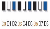
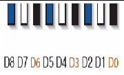
The physical layout of the DIMMs and CPUs on a Sun Blade X6270 Server Module is shown in FIGURE 3-10.
FIGURE 3-10 CPU and DIMM Physical Layout
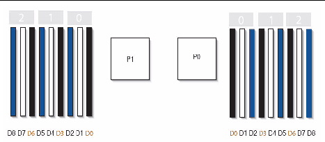
The DIMM population rules for the Sun Blade X6270 Server Module are as follows:
1. Do not populate any DIMM socket next to an empty CPU socket. Each processor contains a separate memory controller.
2. Each CPU can support a maximum of:
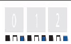
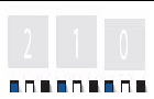
3. Populate DIMMs by location according to the following rules:
For example, populate D8/D5/D2 first; then D7/D4/D1 second; and finally, D6/D3/D0. See FIGURE 3-10.
Note that QR DIMMs are supported only in white sockets if adjacent blue socket contains a QR DIMM.
4. For maximum performance, apply the following rules:
DIMMs come in a variety of ranks: single, dual, or quad. Each DIMM is shipped with a label identifying its rank classification. TABLE 3-3 identifies the corresponding rank classification label shipped with each DIMM.
| Note - This component is a CRU and can be replaced by anyone. |
Use the following procedure to replace a DIMM.
1. Power off the server and remove the server from the chassis.
|
|
Caution - After removing the server from the chassis, ensure that a filler panel is inserted into the empty server slot to reduce the possibility of a system shut down. |
2. Remove the cover from the server.
For details, see Remove or Install Server Cover.
3. To replace a faulty DIMM, perform the following steps; otherwise, proceed to Step 4.
a. Identify the location of the faulty DIMM by pressing the fault remind button on the motherboard, see FIGURE 3-11.
FIGURE 3-11 Fault Remind Button and LED Locations

b. To remove the DIMM do the following:
i. Rotate both DIMM slot ejectors outward as far as they will go.
The DIMM is partially ejected from the socket. See FIGURE 3-12.
ii. Carefully lift the DIMM straight up to remove it from the socket.
|
|
Caution - If you are not immediately inserting a replacement DIMM into the empty DIMM socket, you should insert a DIMM filler panel in the socket. For more details, see these sections, Removing or Replacing Filler Panels. |
FIGURE 3-12 DIMM Socket Release and Alignment

4. To install a DIMM do the following:
a. Determine the DIMM socket location to populate.
For details, see DIMM Population Rules
| Note - If the DIMM socket contains a filler panel, you will need to remove the DIMM filler panel prior to installing a DIMM into the DIMM socket. For details, see Remove or Insert Filler Panels |
b. Ensure that the ejector lever at each end of the memory socket are fully open (rotated outward) to accept the new DIMM.
c. Ensure that the DIMM ejector levers are open (angled outward) then align the DIMM notch to the DIMM connector key. See FIGURE 3-12.
d. Using both thumbs, press the DIMM straight down into the DIMM connector slot until both ejector levers close, locking the DIMM in to the socket.
| Note - The DIMMs must be inserted evenly, straight down into the DIMM connector slot, until the ejector levers lock into place. |
e. Verify that the DIMM ejector levers are upright, seated, and tight. Press on ejector levers to ensure that they are engaged properly.
5. Install the cover on the server.
For instructions, see Install Cover on Server.
The server’s processor provides parity protection on its internal cache memories and error-correcting code (ECC) protection of the data. The system can detect and log the following types of errors:
Advanced ECC corrects up to 4 bits in error on nibble boundaries, as long as they are all in the same DRAM. If a DRAM fails, the DIMM continues to function.
Refer to the Sun Integrated Lights Out Manager 2.0 User’s Guide (820-1188) for information on how to access the error log.
When a single DIMM is marked as faulty by ILOM (for example, fault.memory.intel.dimm.training-failed is listed in the SP Event Log), BIOS might map out the entire memory channel that contains the faulty DIMM as failing, that is, up to three DIMMs. As a result, the memory available to the operating system is reduced.
However, when the Fault Remind button is pressed, only the fault LED associated with the faulty DIMM lights. The fault LEDs for the other two DIMMs in the memory channel remain off. Therefore, you can correctly identify the faulty DIMM. When the faulty DIMM is replaced and the DIMM fault is cleared using ILOM, the memory available to the operating system returns to normal. For instructions for clearing DIMM faults, see the Oracle Integrated Lights Out Manager (ILOM) 3.0 Supplement for the Sun Blade X6270 M2 Server Module (821-0501).
ILOM and BIOS use different formats to identify the location of a faulty DIMM.
TABLE 3-4 shows the mapping of faulty DIMM locations as reported by ILOM and BIOS.
When adding a REM card to a server, you must ensure that the server is equipped with one or more SAS or SATA hard disk drives (HDDs) or solid state drives (SSDs) in disk slots 0 through 3. For further information about the implementation and configuration of RAID on this server, see the Sun Disk Management For x64 Sun Fire and Sun Blade Series Servers Overview Guide (820-6350).
|
|
Caution - Back up all data to an external device prior to adding a REM to a server that does not already have a REM installed. |
Follow these steps to add a REM card.
1. Power off the server and remove the server from the chassis.
|
|
Caution - After removing the server module from the chassis, ensure that a filler panel is inserted into the empty server slot to reduce the possibility of a system shutdown. |
2. Remove the cover from the server module.
For details, see Remove or Install Server Cover.
3. On a new REM card 4620A installation, immediately remove the REM battery from the new REM card.
4. Use two screws to attach the REM battery to the bracket at the front of the server module (see FIGURE 3-13, location 1).
FIGURE 3-13 Possible REM Battery Locations

|
REM battery installed on the bracket at the front of the server module |
|
5. Connect the battery cable to the motherboard and REM card. See FIGURE 3-14.
FIGURE 3-14 REM cable connected to the motherboard

6. Install the new REM card by sliding it at an angle into the support bracket, then pressing it carefully into its connector. See FIGURE 3-15.

|
|
Caution - Step 7will remove all data from the system. Back up your data to an external site before proceeding. |
7. (Optional) If you want to switch your drives from SATA to SAS or from SAS to SATA, you should replace the drives at this time.
For details, see Replacing or Adding a Hard Disk Drive.
8. Install the cover on the server.
For instructions, see Install Cover on Server.
9. Unless you have preloaded software on the SAS/SATA HDDs or SSDs, your server will not have an operating system, or any data. You will need to restore your data from backups, and install the operating system.
With the cover off of the server module, determine whether the REM battery is attached directly onto the motherboard (see FIGURE 3-13, location 1) or on the REM card 4620A (see FIGURE 3-13, location 2).
|
|
1. Remove the existing REM card by sliding it at an angle out of the support bracket. See FIGURE 3-15.
2. Swap the REM battery from the existing REM card to the new REM card.
3. Replace the REM card by sliding the new card at an angle into the support bracket, then pressing it carefully into its connector. See FIGURE 3-15.
4. Install the cover on the server.
For instructions, see Install Cover on Server.
|
|
1. Disconnect the REM card battery cable from the motherboard (see FIGURE 3-14).
2. Remove the existing REM card by sliding the card at an angle out of the support bracket. See FIGURE 3-15.
3. Reconnect the battery cable to the motherboard and the new REM card.
4. Replace the REM card by sliding it at an angle into the support bracket, then pressing it carefully into its connector. See FIGURE 3-15.
5. Install the cover on the server.
For instructions, see Install Cover on Server.
The REM battery should be replaced when indicated in the Sun StorageTek RAID Manager Software User's Guide (820-1177). When replacing the REM battery, you will find the existing battery installed in one of two locations--on the REM card, or on the motherboard--as shown in FIGURE 3-13. Check your installation for the location of the battery.
Follow these steps to replace the REM battery.
1. Remove the cover from the server.
For details, see Remove or Install Server Cover.
2. Disconnect the REM cable and remove the REM card from the chassis.
3. Remove the REM battery from the REM card by removing the four screws securing the old REM battery to the card.
4. Attach the new battery to the REM card with four screws.
5. Install the cover on the server.
For instructions, see Install Cover on Server.
1. Remove the cover from the server.
For details, see Remove or Install Server Cover.
2. Remove the two screws securing the battery to the bracket (see FIGURE 3-16).
3. Place the new battery on bracket and attach it using the two screws.
4. Plug the battery cable into the motherboard.
5. Install the cover on the server.
For instructions, see Install Cover on Server.
FIGURE 3-16 REM Battery Attached to Bracket and Plugged Into Motherboard

Follow these steps to remove and replace a Fabric Expansion Module (FEM) in a Sun Blade X6270 Server Module.
| Note - This component is a CRU and can be replaced by anyone. |
Follow these steps to add or replace the FEM on the server.
1. Power off the server and remove the server from the chassis.
|
|
Caution - After removing the server from the chassis insert a filler panel into an empty slot to reduce the possibility of a system shutdown. |
2. Remove the cover from the server.
For details, see Remove or Install Server Cover.
3. Perform one of the following:
4. Perform the following steps to install the FEM board:
a. Slide the FEM board at an angle into the support bracket
b. Press the FEM board carefully into the connector.
See FIGURE 3-17.
FIGURE 3-17 Inserting the FEM Board

5. Install the cover on the server.
For details, see Install Cover on Server.
| Note - This component is a FRU and should be replaced only by qualified service technicians. Contact your Sun service representative for assistance. |
Follow these steps to replace a CPU and its heatsink in a Sun Blade X6270 Server Module.
1. Power off the server and remove the server from the chassis.
|
|
Caution - Do not operate the system with empty slots. Always insert a filler panel into an empty slot to reduce the possibility of system shut down. |
2. Remove the cover from the server.
For details, see Remove or Install Server Cover.
3. To replace a faulty CPU, perform the following steps; otherwise, proceed to Step 4.
a. Press the fault remind button on the motherboard to illuminate the LED for the CPU that has failed.
See FIGURE 3-18
FIGURE 3-18 Fault Remind Button Location

b. To remove the heatsink covering the faulty CPU, perform the following steps:
i. Hold down the top of the heatsink to prevent it from tipping unevenly while you alternately loosen the spring-loaded mounting screws that secure the heatsink to the motherboard.
ii. Turn the screws 180 degrees at a time, and then remove the screws when they are detached.
See FIGURE 3-19.
iii. Twist the heatsink slightly to lift it off the board. Turn the heatsink upside down and allow the spring in each of the mounting holes to fall out into your hand.
FIGURE 3-19 Remove Heatsink and CPU

| Note - Set the heatsink upside down on a clean, flat surface to prevent the thermal grease from contaminating other components. |
c. To remove the faulty CPU from the CPU socket, perform the following steps:
See FIGURE 3-19.
i. Pivot the socket lever up, into the fully open position.
ii. Open the hinged plate that covers the CPU until it is in the fully open position.
iii. Lift the CPU out of the socket, leaving the lever and plate in the open position.
4. To install (or reinstall) a CPU, perform the following steps and see FIGURE 3-20.
a. Determine the CPU socket location to populate, then if you are replacing the existing CPU with a new CPU proceed to Step 4b; otherwise, perform one of the following tasks before proceeding to Step 4b:
b. Ensure that the CPU socket release lever and retainer plate are in the fully open position then align the CPU with the CPU socket and gently set the CPU onto the pins in the socket.
| Note - Use the alignment keys in the CPU socket to match the alignment notches on the sides of the CPU. |
| Note - Mixing CPU speeds is not supported. Install two identical CPUs in your server. |
FIGURE 3-20 Install CPU and Heatstink

c. When the CPU is fully seated in the socket, pivot the hinged retainer plate down onto the top of the CPU.
See the insert in the first (1) figure shown in FIGURE 3-20.
d. Pivot the release lever down and into the locked position, at the side of the socket.
The release lever must lock down the retainer plate as you close the lever.
5. To install (or reinstall) the heat sink over the CPU socket, perform the following steps.
a. Use the syringe (supplied with the new or replacement CPU) to apply approximately 0.1 ml of thermal grease to the center of the top of the CPU. Do not distribute the grease.
b. Turn the heatsink upright and reinsert the mounting screws.
See the second (2) figure shown in FIGURE 3-20.
|
|
Caution - Avoid moving the heatsink after it has contacted the top of the CPU. Too much movement could disturb the layer of thermal grease, leading to component damage. |
c. Carefully position and align the heatsink over the CPU.
| Note - The heatsink is not symmetrical, and it must be aligned before you place it on the CPU. |
d. Lower the heatsink onto the CPU, aligning the mounting screws with their holes on the motherboard.
e. Using an allen wrench, alternately tighten the two heatsink mounting screws, 180 degrees at a time, until each spring is completely compressed.
Tighten the screws to 7 in.-lbs (0.8 Nm).
6. Reinstall the cover on the server.
For details, see Install Cover on Server.
| Note - This component is a FRU and should be replaced only by qualified service technicians. Contact your Sun Service representative for assistance. |
To remove the motherboard enclosure from service or to return the motherboard enclosure to service, follow these steps:
1. To remove the motherboard enclosure from service, perform the following:
a. Power off the server and remove the server from the chassis.
b. Remove the cover from the server.
For details, see Remove or Install Server Cover.
c. Remove all replaceable components from the motherboard and place them on an antistatic surface.
See FIGURE 3-21.
|
|
Caution - You must return each HDD to the bay from which it was removed. Use an adhesive note or another method to temporarily label the HDDs after you remove them. |
| Note - The server module enclosure, the motherboard, and hard drive backplanes are all part of the motherboard FRU. |
FIGURE 3-21 Remove Replaceable Components from Motherboard

The motherboard enclosure is prepared for service.
2. To return the motherboard enclosure to service, follow these steps:
a. Reinstall the replaceable components on the motherboard.
For instructions for reinstalling the replaceable components, see the procedures referenced in Step 1c of this procedure; or see the procedures in the “Install Server Module Options” chapter in the Sun Blade X6270 Server Module Installation Guide.
For instructions, see Remove or Install Server Cover
c. Install the server module into a powered-on chassis.
For instructions, see “Install Server Module Into A Powered-On Chassis” in the Sun Blade X6270 Server Module Installation Guide.
For instructions, see Power On the Server Module.
| Sun Blade X6270 Server Module Service Manual | 820-6178-13 |
Copyright © 2010, Oracle and/or its affiliates. All rights reserved.

 Remove Cover From Server