| A P P E N D I X E |
|
Configuring a Windows 200x Server or Windows 200x Advanced Server |
This appendix provides platform-specific host installation and configuration information to use when you connect a Sun StorEdge 3310 SCSI array to a host running the Windows 2000 Server, Windows 2000 Advanced Server, Windows 2003 Server, or Windows 2003 Advanced Server OS. For convenience, these platforms are referred to collectively in this document as "Windows 200x server."
The information in this appendix supplements the cabling steps presented in Chapter 4, and covers the following steps:
The RAID controller can be configured by means of a host system running a VT100 terminal emulation program or by a Windows terminal emulation program such as HyperTerminal.
|
Note - You can also monitor and configure a RAID array over an IP network using the firmware application or the Sun StorEdge Configuration Service program after you assign an IP address to the array. For details, see Section 4.12, Setting Up Out-of-Band Management Over Ethernet or refer to the Sun StorEdge 3000 Family Configuration Service User's Guide. |
1. Use a null modem serial cable to connect the COM port of the RAID array to an unused serial port on your host system.
A null modem cable has serial signals swapped for connecting to a standard serial interface.
|
Note - A DB9-to-DB25 serial cable adapter is included in your package contents to connect the serial cable to a DB25 serial port on your host if you do not have a DB9 serial port. |
3. On the Windows 200x server, select Start  Programs
  Accessories
  Communications
  HyperTerminal.
4. Type a name and choose an icon for the connection.
5. In the Connect To window, choose the COM port from the Connect Using: drop-down menu that is connected to the array.
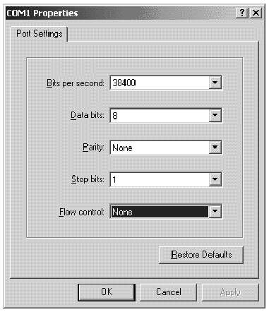
7. In the Properties window, set the serial port parameters using the drop-down menus.

8. To save the connection and its settings, select File  Save.
Save.
The connection filename is connection_name where connection_name is the name you gave this HyperTerminal connection when you created it.
9. To make a connection shortcut on your desktop, select Start  Find
Find  For Files or Folders. Enter the connection_name and click the Search Now button. Highlight and right-click on the filename in the Search Results window, select Create Shortcut, and click Yes.
You are now ready to configure your array.
To access the array through a serial port, use the HyperTerminal connection you configured in Section E.1, Setting Up the Serial Port Connection or install a VT100 terminal emulation program and use the parameters described there.
To access the array through an Ethernet connection, follow the procedures in Section 4.12, Setting Up Out-of-Band Management Over Ethernet. To access the command prompt described there from a Windows 200x Server or Windows 200x Advanced Server, perform this step:
 Choose Programs
  Accessories
  Command Prompt.
Before beginning this procedure, make sure that you are using a supported SCSI host bus adapter (HBA) such as an Adaptec 39160. Refer to the release notes for your array for current information about which HBAs are supported.
Also make sure that you are using a supported driver for your HBA. For the Adaptec 39160, use FMS V4.0a or later.
1. Boot your system and verify that the host bus adapter (HBA) basic input/output system (BIOS) recognizes your new SCSI device(s).
|
Note - While your system is starting up, you should see your new SCSI device(s). |
2. If a Found New Hardware Wizard is displayed, click Cancel.
You are now ready to format your new device(s).
3. Open the Disk Management folder.
a. Right-click on the My Computer icon to display a pop-up menu.
c. Select the Disk Management folder.
d. If a Write Signature and Upgrade Disk Wizard is displayed, click Cancel.
A "Connecting to Logical Disk Manager Server" status message is displayed.
4. Select your new device when it is displayed.
5. Right-click in the Unallocated partition of your device to display a pop-up menu.
6. Select Create Partition from the pop-up menu.
A Create Partition Wizard is displayed.
8. Select Primary partition and click Next.
9. Specify the amount of disk space to use or accept the default value, and click Next.
10. Assign a drive letter if desired and click Next.
11. Select Format this partition with the following settings.
a. Specify NTFS as the File system to use.
b. Make sure the Perform a Quick Format checkbox is checked.
A confirmation dialog displays the settings you have specified.
The new partition is formatted and the formatted partition is identified as NTFS in the Computer Management window.
13. Repeat these steps for any other new partitions and devices you want to format.
Copyright © 2007, Dot Hill Systems Corporation. All rights reserved.