| Skip Navigation Links | |
| Exit Print View | |

|
Oracle Solaris Cluster 3.3 With Sun StorEdge T3 or T3+ Array Manual SPARC Platform Edition |
| Skip Navigation Links | |
| Exit Print View | |

|
Oracle Solaris Cluster 3.3 With Sun StorEdge T3 or T3+ Array Manual SPARC Platform Edition |
1. Installing and Configuring a Sun StorEdge T3 or T3+ Array
Installing Sun StorEdge T3 and T3+ Arrays
How to Install a Storage Array in a New Cluster Using a Single-Controller Configuration
How to Install a Storage Array in a New Cluster, Using a Partner-Group Configuration
How to Add a Storage Array to an Existing Cluster, Using a Single-Controller Configuration
How to Add a Storage Array to an Existing Cluster, Using a Partner-Group Configuration
Configuring Sun StorEdge T3 and T3+ Arrays
How to Create a Logical Volume
How to Remove a Logical Volume
This section contains the procedures about how to install storage arrays in a cluster. The following table lists these procedures.
Table 1-1 Task Map: Installing a Storage Array
|
Use this procedure to install and configure the first storage array in a new cluster, using a single-controller configuration. Perform the steps in this procedure in conjunction with the procedures in the Oracle Solaris Cluster software installation documentation and your server hardware manual.
The following procedures contain instructions for other array-installation situations:
How to Install a Storage Array in a New Cluster, Using a Partner-Group Configuration
How to Add a Storage Array to an Existing Cluster, Using a Single-Controller Configuration
How to Add a Storage Array to an Existing Cluster, Using a Partner-Group Configuration
Note - When you upgrade firmware on a storage device or on an enclosure, redefine the stripe size of a LUN, or perform other LUN operations, a device ID might change unexpectedly. When you perform a check of the device ID configuration by running the cldevice check command, the following error message appears on your console if the device ID changed unexpectedly.
device id for nodename:/dev/rdsk/cXtYdZsN does not match physical
device's id for ddecimalnumber, device may have been replaced.
To fix device IDs that report this error, run the cldevice repair command for each affected device.
To install host adapters, see the documentation that shipped with your host adapters and nodes.
To install FC hubs/switches, see the documentation that shipped with your FC hub/switch hardware.
Note - If you are using two FC switches and Sun SAN software to create a storage area network (SAN), seeSAN Solutions in an Oracle Solaris Cluster Environment in Oracle Solaris Cluster 3.3 Hardware Administration Manual for more information.
This RARP server enables you to assign an IP address to the new storage array by using each storage array's unique MAC address.
To set up a RARP server, see the Sun StorEdge T3 and T3+ Array Installation, Operation, and Service Manual.
To install a media interface adapter (MIA), see the Sun StorEdge T3 and T3+ Array Configuration Guide.
The GBICs or SFPs let you connect the FC hubs/switches to the storage array that you are installing. To install an FC hub/switch GBIC or an SFP, see the documentation that shipped with your FC hub/switch hardware.
To install a fiber-optic cable, see the Sun StorEdge T3 and T3+ Array Configuration Guide.
Figure 1-1 Installing a Single-Controller Configuration
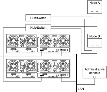
Note - Figure 1-1 shows how to cable two storage arrays to enable data sharing and host-based mirroring. This configuration prevents a single-point of failure.
Note - The storage array might require a few minutes to boot.
To power on a storage array, see the Sun StorEdge T3 and T3+ Array Installation, Operation, and Service Manual.
To configure the storage array with logical volumes, see the Sun StorEdge T3 and T3+ Array Administrator's Guide.
The Oracle Enterprise Manager Ops Center 2.5 software helps you patch and monitor your data center assets. Oracle Enterprise Manager Ops Center 2.5 helps improve operational efficiency and ensures that you have the latest software patches for your software. Contact your Oracle representative to purchase Oracle Enterprise Manager Ops Center 2.5.
Additional information for using the Oracle patch management tools is provided in Oracle Solaris Administration Guide: Basic Administration at http://docs.sun.com. Refer to the version of this manual for the Oracle Solaris OS release that you have installed.
If you must apply a patch when a node is in noncluster mode, you can apply it in a rolling fashion, one node at a time, unless instructions for a patch require that you shut down the entire cluster. Follow the procedures in How to Apply a Rebooting Patch (Node) in Oracle Solaris Cluster System Administration Guide to prepare the node and to boot it in noncluster mode. For ease of installation, consider applying all patches at the same time. That is, apply all patches to the node that you place in noncluster mode.
For required firmware, see the Sun System Handbook.
To verify and assign a target address, see the Sun StorEdge T3 and T3+ Array Configuration Guide.
To reboot or reset a storage array, see the Sun StorEdge T3 and T3+ Array Installation, Operation, and Service Manual.
To install the Oracle Solaris operating environment, see your Oracle Solaris Cluster software installation documentation. For the location of required Oracle Solaris patches and installation instructions for Oracle Solaris Cluster software support, see your Oracle Solaris Cluster release notes documentation. For a list of required Oracle Solaris patches for storage array support, see the Sun StorEdge T3 and T3+ Array Release Notes.
See Also
To continue with Oracle Solaris Cluster software installation tasks, see your Oracle Solaris Cluster software installation documentation.
Use this procedure to install and configure the first storage array partner groups in a new cluster. Perform the steps in this procedure in conjunction with the procedures in the Oracle Solaris Cluster software installation documentation and your server hardware manual.
Make certain that you are using the correct procedure. This procedure contains instructions about how to install a partner group into a new cluster, before the cluster is operational. The following procedures contain instructions for other array-installation situations:
How to Add a Storage Array to an Existing Cluster, Using a Partner-Group Configuration
How to Install a Storage Array in a New Cluster Using a Single-Controller Configuration
How to Add a Storage Array to an Existing Cluster, Using a Single-Controller Configuration
Note - When you upgrade firmware on a storage device or on an enclosure, redefine the stripe size of a LUN, or perform other LUN operations, a device ID might change unexpectedly. When you perform a check of the device ID configuration by running the cldevice check command, the following error message appears on your console if the device ID changed unexpectedly.
device id for nodename:/dev/rdsk/cXtYdZsN does not match physical
device's id for ddecimalnumber, device may have been replaced.
To fix device IDs that report this error, run the cldevice repair command for each affected device.
To install host adapters, see the documentation that shipped with your host adapters and nodes.
To install an FC switch, see the documentation that shipped with your switch hardware.
Note - If you are using two FC switches and Sun SAN software to create a storage area network (SAN), see SAN Considerations for more information.
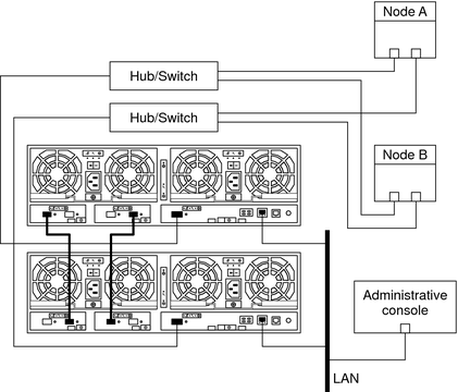
Figure 1-2 Installing a Partner-Group Configuration
To install a media interface adapter (MIA), see the Sun StorEdge T3 and T3+ Array Configuration Guide.
To install a GBIC or an SFP to an FC switch, see the documentation that shipped with your FC switch hardware.
This RARP server enables you to assign an IP address to the new storage arrays. Assign an IP address by using the storage array's unique MAC address. For the procedure about how to set up a RARP server, see the Sun StorEdge T3 and T3+ Array Installation, Operation, and Service Manual.
To install fiber-optic, Ethernet, and interconnect cables, see the Sun StorEdge T3 and T3+ Array Installation, Operation, and Service Manual.
To power on the storage arrays and verify the hardware configuration, see the Sun StorEdge T3 and T3+ Array Installation, Operation, and Service Manual.
Use the telnet command to access the master controller unit and administer the storage arrays. To administer the storage array network addresses and settings, see the Sun StorEdge T3 and T3+ Array Installation, Operation, and Service Manual.
The master controller unit is the storage array that has the interconnect cables attached to the second port of each interconnect card, when viewed from the rear of the storage arrays. For example, Figure 1-2 shows the master controller unit of the partner group as the lower storage array. In this diagram, the interconnect cables are connected to the second port of each interconnect card on the master controller unit.
For partner-group configurations, use the telnet command to access the master controller unit. Install the required controller firmware.
The Oracle Enterprise Manager Ops Center 2.5 software helps you patch and monitor your data center assets. Oracle Enterprise Manager Ops Center 2.5 helps improve operational efficiency and ensures that you have the latest software patches for your software. Contact your Oracle representative to purchase Oracle Enterprise Manager Ops Center 2.5.
Additional information for using the Oracle patch management tools is provided in Oracle Solaris Administration Guide: Basic Administration at http://docs.sun.com. Refer to the version of this manual for the Oracle Solaris OS release that you have installed.
If you must apply a patch when a node is in noncluster mode, you can apply it in a rolling fashion, one node at a time, unless instructions for a patch require that you shut down the entire cluster. Follow the procedures in How to Apply a Rebooting Patch (Node) in Oracle Solaris Cluster System Administration Guide to prepare the node and to boot it in noncluster mode. For ease of installation, consider applying all patches at the same time. That is, apply all patches to the node that you place in noncluster mode.
For required firmware, see the Sun System Handbook.
To verify and assign a target address to a storage array, see the Sun StorEdge T3 and T3+ Array Configuration Guide.
For more information, see the Sun StorEdge T3 and T3+ Array Administrator's Guide.
For more information, see the Sun StorEdge T3 and T3+ Array Administrator's Guide.
For more information about how to correct the situation if both controllers are not online, see the Sun StorEdge T3 and T3+ Array Administrator's Guide.
To create and initialize a logical volume, see the Sun StorEdge T3 and T3+ Array Administrator's Guide. To mount a logical volume, see the Sun StorEdge T3 and T3+ Array Installation, Operation, and Service Manual.
To reboot or reset a storage array, see the Sun StorEdge T3 and T3+ Array Installation, Operation, and Service Manual.
To install the Oracle Solaris operating environment, see How to Install Solaris Software in Oracle Solaris Cluster Software Installation Guide
# devfsadm -C
# luxadm display
See Also
To continue with Oracle Solaris Cluster software installation tasks, see your Oracle Solaris Cluster software installation documentation.
This procedure contains instructions about how to add a new storage array to a running cluster in a single-controller configuration. The following procedures contain instructions for other array-installation situations:
How to Add a Storage Array to an Existing Cluster, Using a Partner-Group Configuration
How to Install a Storage Array in a New Cluster Using a Single-Controller Configuration
How to Install a Storage Array in a New Cluster, Using a Partner-Group Configuration
This procedure defines Node A as the node with which you begin working. Node B is another node in the cluster.
This procedure provides the long forms of the Oracle Solaris Cluster commands. Most commands also have short forms. Except for the forms of the command names, the commands are identical.
This RARP server enables you to assign an IP address to the new storage array by using the storage array's unique MAC address.
To set up a RARP server, see the Sun StorEdge T3 and T3+ Array Installation, Operation, and Service Manual.
If you are not adding a StorEdge T3+ array, skip this step.
To install a media interface adapter (MIA), see the Sun StorEdge T3 and T3+ Array Configuration Guide.
The GBICs or SFPs enables you to connect the FC hubs/switches to the storage array that you are adding.
To install an FC hub/switch GBIC or an SFP, see the documentation that shipped with your FC hub/switch hardware.
Note - If you are using two FC switches and Sun SAN software to create a storage area network (SAN), see SAN Solutions in an Oracle Solaris Cluster Environment in Oracle Solaris Cluster 3.3 Hardware Administration Manual for more information.
Note - The storage array might require a few minutes to boot.
To power on a storage array, see the Sun StorEdge T3 and T3+ Array Installation, Operation, and Service Manual.
The Oracle Enterprise Manager Ops Center 2.5 software helps you patch and monitor your data center assets. Oracle Enterprise Manager Ops Center 2.5 helps improve operational efficiency and ensures that you have the latest software patches for your software. Contact your Oracle representative to purchase Oracle Enterprise Manager Ops Center 2.5.
Additional information for using the Oracle patch management tools is provided in Oracle Solaris Administration Guide: Basic Administration at http://docs.sun.com. Refer to the version of this manual for the Oracle Solaris OS release that you have installed.
If you must apply a patch when a node is in noncluster mode, you can apply it in a rolling fashion, one node at a time, unless instructions for a patch require that you shut down the entire cluster. Follow the procedures in How to Apply a Rebooting Patch (Node) in Oracle Solaris Cluster System Administration Guide to prepare the node and to boot it in noncluster mode. For ease of installation, consider applying all patches at the same time. That is, apply all patches to the node that you place in noncluster mode.
For required firmware, see the Sun System Handbook.
If the target address for this array is already unique, skip this step.
To verify and assign a target address, see the Sun StorEdge T3 and T3+ Array Configuration Guide.
To install a fiber-optic cable, see the Sun StorEdge T3 and T3+ Array Configuration Guide.
Figure 1-3 Adding a Single-Controller Configuration: Part I
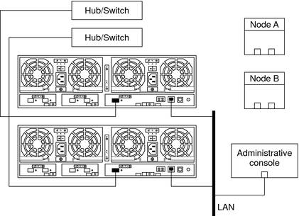
Note - Figure 1-3 shows how to cable two storage arrays to enable data sharing and host-based mirroring. This configuration prevents a single-point of failure.
To create a logical volume, see the Sun StorEdge T3 and T3+ Array Administrator's Guide.
Record this information because you use this information in Step 40 and Step 41 of this procedure to return resource groups and device groups to these nodes.
Use the following command:
# clresourcegroup status +
# cldevicegroup status +
# clnode evacuate
This product requires the following packages.
# pkginfo | egrep Wlux
system    SUNWluxd   Sun Enterprise Network Array sf Device Driver
system    SUNWluxdx  Sun Enterprise Network Array sf Device Driver
                                    (64-bit)
system    SUNWluxl   Sun Enterprise Network Array socal Device Driver
system    SUNWluxlx  Sun Enterprise Network Array socal Device Driver
                                    (64-bit)
system    SUNWluxop  Sun Enterprise Network Array firmware and utilities
If this is not the first FC host adapter on Node A, skip to Step 16. If you do not need to install a host adapter in Node A, skip to Step 35.
The storage array packages are located in the Product directory of the Oracle Solaris DVD. Add any necessary packages.
To shut down and power off a node, see your Oracle Solaris Cluster system administration documentation.
To install a host adapter, see the documentation that shipped with your host adapter and node.
To boot a node in noncluster mode, see Chapter 3, Shutting Down and Booting a Cluster, in Oracle Solaris Cluster System Administration Guide.
The Oracle Enterprise Manager Ops Center 2.5 software helps you patch and monitor your data center assets. Oracle Enterprise Manager Ops Center 2.5 helps improve operational efficiency and ensures that you have the latest software patches for your software. Contact your Oracle representative to purchase Oracle Enterprise Manager Ops Center 2.5.
Additional information for using the Oracle patch management tools is provided in Oracle Solaris Administration Guide: Basic Administration at http://docs.sun.com. Refer to the version of this manual for the Oracle Solaris OS release that you have installed.
If you must apply a patch when a node is in noncluster mode, you can apply it in a rolling fashion, one node at a time, unless instructions for a patch require that you shut down the entire cluster. Follow the procedures in How to Apply a Rebooting Patch (Node) in Oracle Solaris Cluster System Administration Guide to prepare the node and to boot it in noncluster mode. For ease of installation, consider applying all patches at the same time. That is, apply all patches to the node that you place in noncluster mode.
For required firmware, see the Sun System Handbook.
To install an FC host adapter GBIC or an SFP, see your host adapter documentation. To install a fiber-optic cable, see the Sun StorEdge T3 and T3+ Array Configuration Guide.
Figure 1-4 Adding a Single-Controller Configuration: Part II
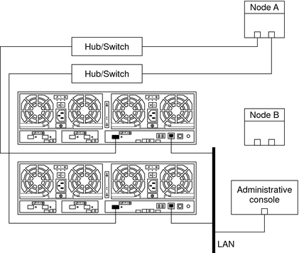
For a list of required Oracle Solaris patches for storage array support, see the Sun StorEdge T3 and T3+ Array Release Notes.
To shut down and power off a node, see your Oracle Solaris Cluster system administration documentation.
# boot -r
To label a logical volume, see the Sun StorEdge T3 and T3+ Array Administrator's Guide.
# cldevice list -n NodeA -v
This product requires the following packages.
# pkginfo | egrep Wlux
system    SUNWluxd       Sun Enterprise Network Array sf Device Driver
system    SUNWluxdx       Sun Enterprise Network Array sf Device Driver
                                    (64-bit)
system    SUNWluxl       Sun Enterprise Network Array socal Device Driver
system    SUNWluxlx       Sun Enterprise Network Array socal Device Driver
                                    (64-bit)
system    SUNWluxop       Sun Enterprise Network Array firmware and utilities
If this is not the first FC host adapter on Node B, skip to Step 29. If you do not need to install a host adapter, skip to Step 34.
The storage array packages are located in the Product directory of the Oracle Solaris DVD. Add any necessary packages.
To shut down and power off a node, see your Oracle Solaris Cluster system administration documentation.
For more information, see your Oracle Solaris Cluster system administration documentation.
To install a host adapter, see the documentation that shipped with your host adapter and node.
To boot a node in noncluster mode, see Chapter 3, Shutting Down and Booting a Cluster, in Oracle Solaris Cluster System Administration Guide.
The Oracle Enterprise Manager Ops Center 2.5 software helps you patch and monitor your data center assets. Oracle Enterprise Manager Ops Center 2.5 helps improve operational efficiency and ensures that you have the latest software patches for your software. Contact your Oracle representative to purchase Oracle Enterprise Manager Ops Center 2.5.
Additional information for using the Oracle patch management tools is provided in Oracle Solaris Administration Guide: Basic Administration at http://docs.sun.com. Refer to the version of this manual for the Oracle Solaris OS release that you have installed.
If you must apply a patch when a node is in noncluster mode, you can apply it in a rolling fashion, one node at a time, unless instructions for a patch require that you shut down the entire cluster. Follow the procedures in How to Apply a Rebooting Patch (Node) in Oracle Solaris Cluster System Administration Guide to prepare the node and to boot it in noncluster mode. For ease of installation, consider applying all patches at the same time. That is, apply all patches to the node that you place in noncluster mode.
For required firmware, see the Sun System Handbook.
To install an FC hub/switch GBIC or an SFP, see the documentation that shipped with your FC hub/switch hardware.
Note - If you are using two FC switches and Sun SAN software to create a storage area network (SAN), see SAN Solutions in an Oracle Solaris Cluster Environment in Oracle Solaris Cluster 3.3 Hardware Administration Manual for more information.
To install an FC host adapter GBIC or an SFP, see your host adapter documentation. To install a fiber-optic cable, see the Sun StorEdge T3 and T3+ Array Configuration Guide.
Figure 1-5 Adding a Single-Controller Configuration: Part III

For a list of required Oracle Solaris patches for storage array support, see the Sun StorEdge T3 and T3+ Array Release Notes.
To shut down and power off a node, see your Oracle Solaris Cluster system administration documentation.
# boot -r
# cldevice list -n NodeB -v
Do the following for each device group that you want to return to the original node.
# cldevicegroup switch -n nodename devicegroup1[ devicegroup2 …]
The node to which you are restoring device groups.
The device group or groups that you are restoring to the node.
Do the following for each resource group that you want to return to the original node.
# clresourcegroup switch -n nodename resourcegroup1[ resourcegroup2 …]
For failover resource groups, the node to which the groups are returned. For scalable resource groups, the node list to which the groups are returned.
The resource group or groups that you are returning to the node or nodes.
For more information, see your Solaris Volume Manager or Veritas Volume Manager documentation.
This procedure contains instructions for adding new storage array partner groups to a running cluster. The following procedures contain instructions for other array-installation situations:
How to Install a Storage Array in a New Cluster, Using a Partner-Group Configuration
How to Install a Storage Array in a New Cluster Using a Single-Controller Configuration
How to Add a Storage Array to an Existing Cluster, Using a Single-Controller Configuration
This procedure provides the long forms of the Oracle Solaris Cluster commands. Most commands also have short forms. Except for the forms of the command names, the commands are identical.
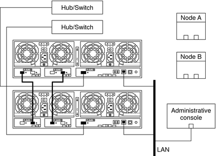
Note - Assign an IP address to the master controller unit only. The master controller unit is the storage array that has the interconnect cables attached to the second port of each interconnect card, as shown in Figure 1-6.
This RARP server enables you to assign an IP address to the new storage arrays. Assign an IP address by using the storage array's unique MAC address. To set up a RARP server, see the Sun StorEdge T3 and T3+ Array Installation, Operation, and Service Manual.
To install interconnect cables, see the Sun StorEdge T3 and T3+ Array Installation, Operation, and Service Manual.
Figure 1-6 Adding a Partner-Group Configuration: Part I
Note - The storage arrays might require several minutes to boot.
To power on storage arrays, see the Sun StorEdge T3 and T3+ Array Installation, Operation, and Service Manual.
Use the telnet command to access the master controller unit and to administer the storage arrays.
To administer the network address and the settings of a storage array, see the Sun StorEdge T3 and T3+ Array Installation, Operation, and Service Manual.
For partner-group configurations, use the telnet command to the master controller unit. If necessary, install the required controller firmware for the storage array.
For the required revision number of the storage array controller firmware, see the Sun StorEdge T3 Disk Tray Release Notes.
To verify and assign a target address to a storage array, see the Sun StorEdge T3 and T3+ Array Configuration Guide.
For more information, see the Sun StorEdge T3 and T3+ Array Administrator's Guide.
For more information, see the Sun StorEdge T3 and T3+ Array Administrator's Guide.
To create and initialize a logical volume, see the Sun StorEdge T3 and T3+ Array Administrator's Guide. To mount a logical volume, see the Sun StorEdge T3 and T3+ Array Installation, Operation, and Service Manual.
To reboot or reset a storage array, see the Sun StorEdge T3 and T3+ Array Installation, Operation, and Service Manual.
To install an MIA, see the Sun StorEdge T3 and T3+ Array Configuration Guide.
To install a GBIC or an SFP to an FC switch, see the documentation that shipped with your FC switch hardware.
To install a fiber-optic cable, see the Sun StorEdge T3 and T3+ Array Installation, Operation, and Service Manual.
Note - If you are using two FC switches and Sun SAN software to create a storage area network (SAN), see SAN Considerations for more information.
Record this information because you use it in Step 30 of this procedure to return resource groups and device groups to these nodes.
Use the following command:
# clresourcegroup status +
# cldevicegroup status +
# clnode evacuate
The following packages are required.
# pkginfo | egrep Wlux
system     SUNWluxd     Sun Enterprise Network Array sf Device Driver
system     SUNWluxdx    Sun Enterprise Network Array sf Device Driver
                                (64-bit)
system     SUNWluxl     Sun Enterprise Network Array socal Device Driver
system     SUNWluxlx    Sun Enterprise Network Array socal Device Driver
                                (64-bit)
system     SUNWluxop    Sun Enterprise Network Array firmware and utilities
system     SUNWluxox    Sun Enterprise Network Array libraries (64-bit)
If this is not the first host adapter on the node, skip to Step 20.
The support packages are located in the Product directory of the Oracle Solaris DVD. Add any missing packages.
To shut down and power off a node, see your Oracle Solaris Cluster system administration documentation.
To install host adapters, see the documentation that shipped with your host adapters and nodes.
To boot nodes, see Chapter 3, Shutting Down and Booting a Cluster, in Oracle Solaris Cluster System Administration Guide.
The Oracle Enterprise Manager Ops Center 2.5 software helps you patch and monitor your data center assets. Oracle Enterprise Manager Ops Center 2.5 helps improve operational efficiency and ensures that you have the latest software patches for your software. Contact your Oracle representative to purchase Oracle Enterprise Manager Ops Center 2.5.
Additional information for using the Oracle patch management tools is provided in Oracle Solaris Administration Guide: Basic Administration at http://docs.sun.com. Refer to the version of this manual for the Oracle Solaris OS release that you have installed.
If you must apply a patch when a node is in noncluster mode, you can apply it in a rolling fashion, one node at a time, unless instructions for a patch require that you shut down the entire cluster. Follow the procedures in How to Apply a Rebooting Patch (Node) in Oracle Solaris Cluster System Administration Guide to prepare the node and to boot it in noncluster mode. For ease of installation, consider applying all patches at the same time. That is, apply all patches to the node that you place in noncluster mode.
For required firmware, see the Sun System Handbook.
To install a fiber-optic cable, see the Sun StorEdge T3 and T3+ Array Installation, Operation, and Service Manual.
Note - If you are using two FC switches and Sun SAN software to create a storage area network (SAN), see SAN Considerations for more information.
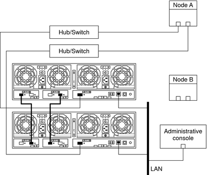
Figure 1-7 Adding a Partner-Group Configuration: Part II
# devfsadm
# cldevice populate
To label a logical volume, see the Sun StorEdge T3 and T3+ Array Administrator's Guide.
# cldevice list -n CurrentNode -v
Do the following for each resource group that you want to return to the original node.
# clresourcegroup switch -n nodename resourcegroup1[ resourcegroup2 …]
For failover resource groups, the node to which the groups are returned. For scalable resource groups, the node list to which the groups are returned.
The resource group or groups that you are returning to the node or nodes.
For more information, see your Veritas Volume Manager documentation.