| C H A P T E R 5 |
|
Servicing Infrastructure Components |
This chapter describes how to replace infrastructure components in the Sun Fire X4170 M2 Server.
| Note - All components covered in this chapter are customer-replaceable units (CRUs). |
The following topics are covered:

|
Caution - Hazardous voltage present.Never attempt to run the server with the top cover removed. |


|
Caution - Equipment damage possible. The top cover must be in place for proper airflow. |
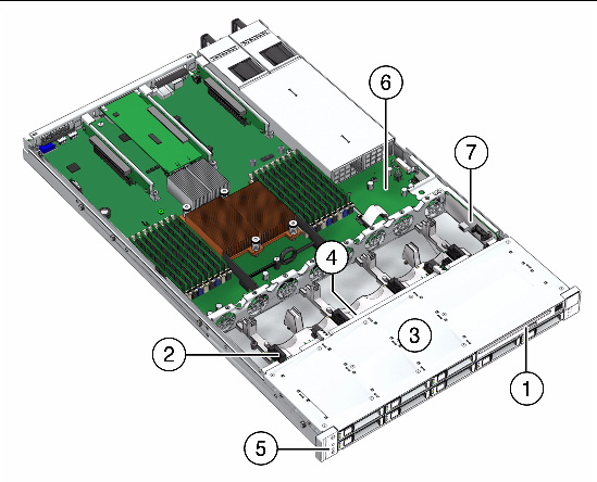
FIGURE 5-1 shows the infrastructure components that are replaceable.
FIGURE 5-1 Location of Infrastructure Components
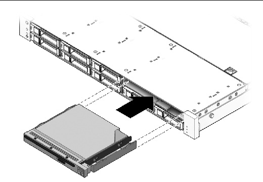
The DVD-ROM drive and front USB connector board are mounted in a removable module that is accessible from the front panel of the system. The DVD/USB module must be removed from the storage drive cage in order to service the disk backplane.
1. Remove media from the drive.
See Power Off the Server.
3. Attach an antistatic wrist strap.
See Performing Electrostatic Discharge and Antistatic Prevention Measures.
4. Remove the server storage drive located below and to the right the DVD/USB module (FIGURE 5-2).
See Server Storage Drive Locations for illustrations of the storage drive locations for the Sun Fire X4170 M2 Server.
5. Release the DVD/USB module from the disk backplane.
Grasp the release tab under the DVD/USB module and pull it out to release the module from the disk backplane (FIGURE 5-2).
6. Slide the DVD/USB module out of the storage drive cage.
7. Place the module on an antistatic mat.
FIGURE 5-2 Removing the DVD/USB Module

1. Push the DVD/USB module release tab back into the system.
2. Slide the DVD/USB module into the storage drive cage until it seats (FIGURE 5-3).
3. Install the storage drive you removed during the DVD/USB module removal procedure.
Verify that the Power/OK LED is lit.
FIGURE 5-3 Installing the DVD/USB Module

|
Caution - Ensure that all power is removed from the server before removing or installing the fan board. You must disconnect the power cables before performing these procedures. |
1. Prepare the server for service.
a. Power off the server and disconnect the power cord (or cords) from the power supply (or supplies).
See Power Off the Server.
b. Extend the server to the maintenance position.
See Extending the Server to the Maintenance Position.
| Note - If you are removing the fan board to access the paddle board or storage drive cage, you must remove the server from the rack. See Removing the Server From the Rack. |
c. Attach an antistatic wrist strap.
See Performing Electrostatic Discharge and Antistatic Prevention Measures.
2. Remove the fan board (FIGURE 5-4).
a. Remove the four fan modules.
See Remove Fan Module.
b. Disconnect the storage drive cables from the disk backplane.
To disconnect each cable, press the latch, push in toward the connector, and then pull out to remove the cable.
c. Disconnect the fan power cable and the fan ribbon cable (FIGURE 5-4 [1].
d. Remove the Phillips screw that secures the fan board to the chassis [2].
e. Press the two release tabs and pull the fan board toward the front of the server to disengage the fan board from the mushroom standoffs [2].
There are eight mushroom standoffs in the chassis for the fan board.
f. Remove the fan board from the server chassis and place it on an antistatic mat [3].
FIGURE 5-4 Removing the Fan Board

1. Lower the fan board over the mushroom standoffs in the chassis floor (FIGURE 5-5 [1]).
FIGURE 5-5 Installing the Fan Board
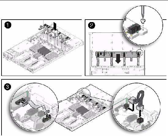
2. Slide the fan board toward the rear of the server to engage the mushroom standoffs [2].
3. Install the Phillips screw to secure the fan board to the chassis [2].
4. Reconnect the fan ribbon cable and the fan power cable between the paddle board to the fan board [3].
See Install Fan Module.
6. Reconnect the storage drive cables to the disk backplane.
7. Return the server to operation.
b. Return the server to the normal rack position.
See Returning the Server to the Normal Rack Position.
c. Reconnect the power cord (or cords) to the power supply (or supplies) and power on the server.
Verify that the AC Present LED is lit.
You must remove the storage drive cage to access the following components:

|
Caution - Ensure that all power is removed from the server before removing or installing the storage drive cage. You must disconnect the power cables before performing this procedure. |
1. Prepare the server for service.
a. Power off the server and disconnect the power cord (or cords) from the power supply (or supplies).
See Power Off the Server.
b. Remove the server from the rack.
See Removing the Server From the Rack.
c. Attach an antistatic wrist strap.
See Performing Electrostatic Discharge and Antistatic Prevention Measures.
See Remove Storage Drive.
| Note - Record the drive locations before removing them from the system. You will need to install the storage drives in the correct locations when reassembling the system. |
3. If you are servicing the disk backplane, remove the DVD/USB module.
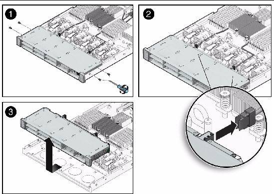
4. Remove the storage drive cage (FIGURE 5-6).
a. Remove the four No. 2 Phillips screws securing the storage drive cage to the chassis [1].
Two screws secure the disk cage to each side of the chassis.
b. To disconnect the cables connected to the disk backplane, grasp the cable connector, press the latch, push in toward the disk backplane, and then pull out to remove the cable [2].
c. Slide the storage drive cage forward to disengage the backplane from the paddle board, then lift the cage up and out of the chassis [3].
d. Set the storage drive cage on an antistatic mat.
FIGURE 5-6 Removing the Storage Drive Cage
1. Install the storage drive cage (FIGURE 5-6).
a. Position the storage drive cage in the chassis over the standoffs in the chassis side walls [3].
b. Slide the storage drive cage back until the disk backplane engages with the paddle board connector [3].
c. Connect the storage drive cables [2].
Press the connector into its socket until it snaps into place.
d. Replace the four No. 2 Phillips screws securing the storage drive cage to the chassis [1].
Two screws secure the storage drive cage to each side of the chassis.
2. Return the server to operation.
b. Install the server into the rack.
See Reinstalling the Server in the Rack.
c. Install the storage drives.
| Note - Ensure that you are installing the storage drives in the correct drive bays. |
d. Install the DVD/USB module.
e. Return the server to the normal rack position.
See Returning the Server to the Normal Rack Position.
f. Reconnect the power cord (or cords) to the power supply (or supplies) and power on the server.
Verify that the AC Present LED is lit.
Before you can service the disk backplane, you must remove the storage drive cage.

|
Caution - Ensure that all power is removed from the server before removing or installing the disk backplane. You must disconnect the power cables before performing this procedure. |
1. Prepare the server for service.
a. Power off the server and disconnect the power cord (or cords) from the power supply (or supplies).
See Power Off the Server.
b. Remove the server from the rack.
See Removing the Server From the Rack.
c. Attach an antistatic wrist strap.
See Performing Electrostatic Discharge and Antistatic Prevention Measures.
2. Remove all of the storage drives and the DVD/USB drive from the disk drive cage.
See Servicing the DVD/USB Module.
3. Remove the storage drive cage.
See Remove Storage Drive Cage.
4. Remove the two No. 2 Phillips screws securing the disk backplane to the storage drive cage (FIGURE 5-7).
FIGURE 5-7 Removing the Disk Backplane
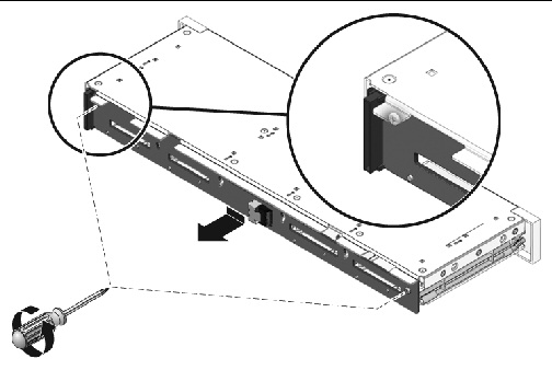
5. Slide the backplane down and off the storage drive cage retention hooks.
6. Place the disk backplane on an antistatic mat.
1. Slide the backplane under the retention hooks on the storage drive cage (FIGURE 5-8 [1, 2]).
2. Install the two No. 2 Phillips screws that secure the backplane to the storage drive cage [3].
3. Install the storage drive cage.
See Install Storage Drive Cage.
4. Install the storage drives and the DVD/USB drive.
See Servicing the DVD/USB Module.
FIGURE 5-8 Installing the Disk Backplane
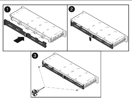
5. Return the server to operation.
b. Install the server into the rack.
See Reinstalling the Server in the Rack.
c. Return the server to the normal rack position.
See Returning the Server to the Normal Rack Position.
d. Reconnect the power cord (or cords) to the power supply (or supplies) and power on the server.
Verify that the AC Present LED is lit.
You must remove the disk backplane to service the front control panel light pipe assemblies.

|
Caution - Ensure that all power is removed from the server before removing or installing the light pipe assembly. You must disconnect the power cables before performing this procedure. |
There are two light pipe assemblies; one on each side of the storage drive cage.
1. Prepare the server for service.
a. Power off the server and disconnect the power cord (or cords) from the power supply (or supplies).
See Power Off the Server.
b. Remove the server from the rack.
See Removing the Server From the Rack.
c. Attach an antistatic wrist strap.
See Performing Electrostatic Discharge and Antistatic Prevention Measures.
2. Remove the storage drive cage.
See Remove Storage Drive Cage.
4. Remove the two No. 2 Phillips screws securing the front control panel light pipe assembly to the storage drive cage (FIGURE 5-9 [1]).
5. Remove the light pipe assembly from the storage drive cage (FIGURE 5-9 [1]).
FIGURE 5-9 Removing the Light Pipe Assembly
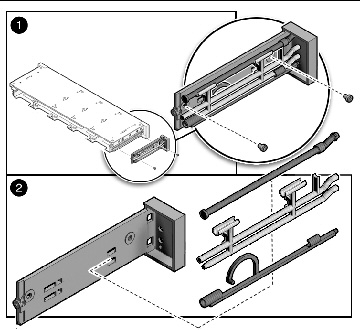
1. Align the light pipe assembly with the mounting holes on the storage drive cage (FIGURE 5-9 [1]).
2. Secure the light pipe assembly with the two No. 2 Phillips screws (FIGURE 5-9 [1]).
3. Install the disk backplane.
4. Install the storage drive cage.
See Install Storage Drive Cage.
5. Return the server to operation.
b. Install the server into the rack.
See Reinstalling the Server in the Rack.
c. Return the server to the normal rack position.
See Returning the Server to the Normal Rack Position.
d. Reconnect the power cord (or cords) to the power supply (or supplies) and power on the server.
Verify that the AC Present LED is lit.
It is easier to service the power distribution board (PDB) with the bus bar attached. If you are replacing a faulty PDB, you must remove the bus bar from the old board and attach it to the new PDB.
You must remove the power distribution board to access and remove the paddle board.
1. Prepare the server for service.
a. Power off the server and disconnect the power cord (or cords) from the power supply (or supplies).
See Power Off the Server.
b. Remove the server from the rack.
See Removing the Server From the Rack.
c. Attach an antistatic wrist strap.
See Performing Electrostatic Discharge and Antistatic Prevention Measures.
See Remove Motherboard.
See Remove Power Supply.
4. Remove the power distribution board (FIGURE 5-10).
a. Disconnect the top cover chassis intrusion switch cable from the power distribution board [1].
b. Remove the No. 2 Phillips screw securing the power distribution board to the chassis [2].
c. Grasp the bus bar and pull the power distribution board bus bar assembly to the right to disengage the power distribution board’s edge connector from the paddle board [3].
d. Lift the power distribution board bus bar assembly up and out of the system [3].
5. Place the power distribution board bus bar assembly on an antistatic mat.
FIGURE 5-10 Removing the Power Distribution Board
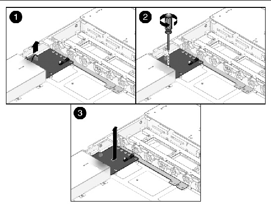
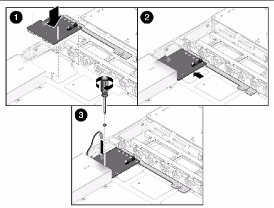
1. Lower the power distribution board bus bar assembly into the chassis (FIGURE 5-11 [1]).
The power distribution board fits over a series of mushroom standoffs in the floor of the chassis.
2. Slide the power distribution board bus bar assembly to the left, until it plugs into the paddle board [2].
3. Install the No. 2 Phillips screw to secure the power distribution board to the chassis [3].
4. Connect the top cover chassis intrusion switch cable to the power distribution board [3].
FIGURE 5-11 Installing the Power Distribution Board
5. Install the power supplies.
See Install Power Supply.
See Install Motherboard.
7. Return the server to operation.
b. Install the server into the rack.
See Reinstalling the Server in the Rack.
c. Return the server to the normal rack position.
See Returning the Server to the Normal Rack Position.
d. Reconnect the power cord (or cords) to the power supply (or supplies) and power on the server.
Verify that the AC Present LED is lit.
The paddle board includes the top cover interlock switch.
1. Prepare the server for service.
a. Power off the server and disconnect the power cord (or cords) from the power supply (or supplies).
See Power Off the Server.
b. Remove the server from the rack.
See Removing the Server From the Rack.
c. Attach an antistatic wrist strap.
See Performing Electrostatic Discharge and Antistatic Prevention Measures.
See Remove Motherboard.
3. Remove the power distribution board.
See Remove Power Distribution Board.
4. Remove the paddle board (FIGURE 5-12).
a. For ease of access to the paddle board, remove the fan module located next to the paddle board.
See Remove Fan Module.
b. Disconnect the fan signal cable and the fan power cable from the paddle board (FIGURE 5-4).
c. Remove the two No. 2 Phillips screws securing the paddle board and its support bracket to the chassis mid wall (FIGURE 5-12 [1]).
FIGURE 5-12 Removing the Paddle Board
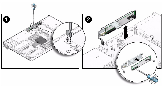
d. Slide the paddle board and bracket toward the rear of the server to disengage the paddle board’s edge connector from the disk backplane [2].
e. Lift the paddle board and its support bracket up and out of the chassis [2].
f. To remove the paddle board from its support bracket, remove the two Phillips screws that secure the paddle board to the bracket [2].
g. Place the paddle board on an antistatic mat.
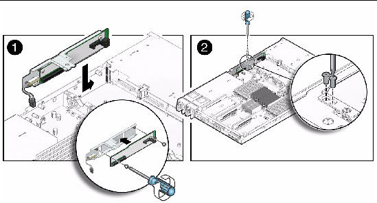
1. Attach the paddle board to the support bracket with two Phillips screws (FIGURE 5-13 [1]).
2. Lower the paddle board and its support bracket into the server chassis and slide it forward to plug it into the disk backplane [1].
3. Secure the paddle board and its support bracket to the chassis mid wall with two No. 2 Phillips screws [2].
4. Reconnect the fan power cable and the fan signal cable to the paddle board (FIGURE 5-5).
5. Replace the fan module located next to the paddle board.
FIGURE 5-13 Installing the Paddle Board
6. Install the power distribution board.
See Install Power Distribution Board.
See Install Motherboard.
8. Return the server to operation.
b. Install the server into the rack.
See Reinstalling the Server in the Rack.
c. Return the server to the normal rack position.
See Returning the Server to the Normal Rack Position.
d. Reconnect the power cord (or cords) to the power supply (or supplies) and power on the server.
Verify that the AC Present LED is lit.
The following topics are covered:

|
Caution - The system supplies power to the cables even when the server is powered off. To avoid personal injury or damage to the server, you must disconnect power cords before servicing the cables. |
1. Prepare the server for service.
a. Power off the server and disconnect the power cord (or cords) from the power supply (or supplies).
See Power Off the Server.
b. Extend the server to the maintenance position.
See Extending the Server to the Maintenance Position.
c. Attach an antistatic wrist strap.
See Performing Electrostatic Discharge and Antistatic Prevention Measures.
2. Remove the storage drive cables (FIGURE 5-14).
a. Untwist the cable tie downs to release the cable(s).
b. To remove the air plenum, remove the Phillips screw that secures it to the motherboard and remove it (FIGURE 4-17 [4]).
c. Using a hex wrench, unscrew the two screws from both CPU heat sinks and remove the heat sinks (FIGURE 4-15 [2]).
Turn the screws alternately one and one half turns until they are fully removed.
d. Twist the heat sinks slightly to break the grease seal, lift off the heat sinks and place them upside down on a flat surface to prevent the thermal grease from contaminating other components.
e. Use an alcohol pad to clean the thermal grease from the bottom of the heat sinks and the top of the CPUs.
Be very careful not to get the thermal grease on your fingers.
f. To disconnect the cables from the host bus adapter (HBA) PCIe card, press the latch, push in toward the connector, and then pull out to remove the cables.
FIGURE 5-14 Removing the Storage Drive Cables From SAS Configuration

g. To disconnect each cable at the disk backplane, press the latch, push in toward the connector, and then pull out to remove the cable.
It is not necessary to remove any of the fan modules to remove the cables.
h. Remove the cables from the chassis.
To install the two storage drive cables--disk 0-3 cable and disk 4-7 cable--in a SAS configuration, do the following (FIGURE 5-14).
1. Install the disk 0-3 cable first.
a. Install the cable connector into the disk backplane.
The connector is on the left side when viewing from the front of the server.
b. Route the cable between the fan modules and between CPU1 and the DDR3 DIMMs.
There is a trough between the fan modules for routing the cable.
c. Plug the cable connector into the connector on the left side of HBA card (the connector that is farther from the power supplies).
2. Install the disk 4-7 cable.
a. Plug the backplane connector(s) into the disk backplane.
The connector is on the right side when viewing from the front of the server.
b. Route the cable between the fan modules and between CPU0 and the DDR3 DIMMs.
There is a trough between the fan modules for routing the cable.
c. Plug the cable connector into the connector on the right side of the HBA card (the connector that is closer to the power supplies).
3. Place the cables into the cable tie downs, and secure them with the tie downs.
4. Install the CPU heat sinks (FIGURE 4-16).
a. Use the thermal grease syringe to apply approximately 0.1 ml of thermal grease to the center of the top of the CPU. Do not distribute the grease.
b. Inspect the heat sinks for dust and lint. Clean if necessary.
c. Orient the heat sinks so that the two screws line up with the mounting studs [3].
d. Carefully position the heat sinks on each CPU, aligning them with the mounting posts to reduce movement after they makes initial contact with the layer of thermal grease [3].

|
Caution - If the heat sink is moved too much during its installation, the layer of thermal grease may not be distributed evenly, leading to component damage. |
e. Tighten the heat sink screws alternately one-half turn until fully seated.
5. Return the server to operation.
b. Return the server to the normal rack position.
See Returning the Server to the Normal Rack Position.
c. Reconnect the power cord (or cords) to the power supply (or supplies) and power on the server.
Verify that the Power/OK LED is lit.
1. Prepare the server for service.
a. Power off the server and disconnect the power cord (or cords) from the power supply (or supplies).
See Power Off the Server.
b. Extend the server to the maintenance position.
See Extending the Server to the Maintenance Position.
c. Attach an antistatic wrist strap.
See Performing Electrostatic Discharge and Antistatic Prevention Measures.
2. (Optional) Remove the PCIe card in the PCIe slot 1 riser for better access to the cables.
3. Remove the cables (FIGURE 5-15).
a. Untwist the cable tie downs to release the cables.
b. Using a hex wrench, unscrew the two screws from both CPU heat sinks and remove the heat sinks (FIGURE 4-17 [2]).
Turn the screws alternately one and one half turns until they are fully removed.
c. Twist the heat sinks slightly to break the grease seal, lift off the heat sinks and place them upside down on a flat surface to prevent the thermal grease from contaminating other components.
d. Use an alcohol pad to clean the thermal grease from the bottom of the heat sinks and the top of the CPUs.
Be very careful not to get the thermal grease on your fingers.
e. Press the latch on the single headed cable and then disconnect the cables from the SATA on-board connectors at the rear of the server.
The SATA connectors are on the motherboard.
f. Disconnect each cable at the disk backplane by pressing the latch, pushing in toward the connector, and then pulling out to remove the cable.
g. Remove the cables from the chassis.
FIGURE 5-15 Removing the Storage Drive Cables From SATA Configuration

To install two storage drive cables, disk 0-3 and disk 4-5 in SATA configuration, do the following (FIGURE 5-15):
1. Install the disk 0-3 cable.
a. Install the cable connector into the left-side connector on the disk backplane.
The connector is on the left side when viewing from the front of the server.
b. Route the cable between the fan modules and between CPU1 and the DDR3 DIMMs.
There is a trough between the fan modules for routing the cable.
c. Plug the other end of the cable into the rear-most, SATA on-board connector on the motherboard.
2. Install the disk 4-5 cable.
a. Install the cable connector into the right-side connector on the disk backplane.
The connector is on the right side when viewing from the front of the server.
b. Route the cable between the fan modules and between CPU0 and the DDR3 DIMMs.
There is a trough between the fan modules for routing the cable.
c. Plug the other end of the cable into the front-most, SATA on-board connector on the motherboard.
3. Place the cables in the cable tie downs, and secure them using the tie downs.
4. Install the CPU heat sinks (FIGURE 4-16).
a. Use the thermal grease syringe to apply approximately 0.1 ml of thermal grease to the center of the top of the CPU. Do not distribute the grease.
b. Inspect the heat sinks for dust and lint. Clean if necessary.
c. Orient the heat sinks so that the two screws line up with the mounting studs [3].
d. Carefully position the heat sinks on each CPU, aligning them with the mounting posts to reduce movement after they makes initial contact with the layer of thermal grease [3].

|
Caution - If the heat sink is moved too much during its installation, the layer of thermal grease may not be distributed evenly, leading to component damage. |
e. Tighten the heat sink screws alternately one-half turn until fully seated [3].
5. Return the server to operation.
b. Return the server to the normal rack position.
See Returning the Server to the Normal Rack Position.
c. Reconnect the power cord (or cords) to the power supply (or supplies) and power on the server.
Verify that the AC Present LED is lit.
1. Remove the storage drive cables from the SAS configuration.
See Remove Storage Drive Cables From a SAS Configuration.
3. Install either a different PCIe card or a PCIe filler panel in the slot from which the HBA card was removed.
4. Install the storage drive cables in the SATA configuration.
See Install Storage Drive Cables in a SATA Configuration.
1. Remove the storage drive cables from the SATA configuration.
See Remove Storage Drive Cables in a SATA Configuration.
2. Install the SAS HBA card in the PCIe slot (any vacant slot other than slot 1).
3. Install the storage drive cables in the SAS configuration.
See Install Storage Drive Cables in a SAS Configuration.
1. Prepare the server for service.
a. Power off the server and disconnect the power cord (or cords) from the power supply (or supplies).
See Power Off the Server.
b. Extend the server to the maintenance position.
See Extending the Server to the Maintenance Position.
c. Attach an antistatic wrist strap.
See Performing Electrostatic Discharge and Antistatic Prevention Measures.
e. Viewing the server from the front, remove the fan from the right-most position.
2. Remove the fan board cables (FIGURE 5-4 [1]).
a. Disconnect and remove the fan power cable.
The fan power cable connects between the paddle board and the fan board.
b. Disconnect and remove the fan signal cable.
The fan signal cable connects between the paddle board and the fan board.
1. Install the fan board cables (FIGURE 5-4 [1]).
a. Connect the fan power cable.
The fan power cable connects between the paddle board and the fan board.
b. Connect the fan signal cable.
The fan signal cable connects between the paddle board and the fan board.
c. Viewing the server from the front, install the fan in the right-most position.
2. Return the server to operation.
b. Return the server to the normal rack position.
See Returning the Server to the Normal Rack Position.
c. Reconnect the power cord (or cords) to the power supply (or supplies) and power on the server.
Verify that the Power/OK LED is lit.
1. Prepare the server for service.
a. Power off the server and disconnect the power cord (or cords) from the power supply (or supplies).
See Power Off the Server.
b. Extend the server to the maintenance position.
See Extending the Server to the Maintenance Position.
c. Attach an antistatic wrist strap.
See Performing Electrostatic Discharge and Antistatic Prevention Measures.
2. Remove the existing power distribution board cable (FIGURE 4-17).
The power distribution board cable connects between the power distribution board and the motherboard.
a. Release the latches on both sides of the cable connector on the power distribution board and pull the cable straight up [1].
b. Release the latches on both sides of the cable connector on the motherboard and pull the cable straight up [1].
The power distribution board cable connects between the power distribution board and the motherboard.
1. Install the power distribution board cable (FIGURE 4-18).
a. Ensure that the latches on the power distribution board connector are in the open position and connect ribbon cable to the connector [4].
Ensure that the ribbon cable connector is seated properly.
b. Ensure that the latches on the motherboard connector are in the open position and connect ribbon cable to the connector [4].
Ensure that the ribbon cable connector is seated properly.
2. Return the server to operation.
b. Return the server to the normal rack position.
See Returning the Server to the Normal Rack Position.
c. Reconnect the power cord (or cords) to the power supply (or supplies) and power on the server.
Verify that the AC Present LED is lit.
Copyright © 2011, Oracle and/or its affiliates. All rights reserved.