| Sun Cooling Door 5200 Installation and User’s Guide |
| C H A P T E R 1 |
|
Preparing to Install |
This chapter provides a summary of what is required to prepare your site for installation of the Sun Cooling Door 5200.
The following information is covered in this chapter:
Sun Cooling Door 5200 can be installed onto the Sun Blade 6048 chassis (part number 594-5971-xx). You can distinguish the newer Sun Blade 6048 chassis by the presence of the rear top and bottom covers that allow for greater airflow control.
| Note - The Sun Cooling Door 5200 should only be installed onto a server rack that has existing holes at its rear to accept the two Sun Cooling Door 5200 adapter brackets. |
Your data center must have the necessary humidity control infrastructure to optimize the cooling performance of the Sun Cooling Door 5200.
Condensation is prevented when the temperature of the water flow remains above the dew point. The dew-point depends on the existing ambient temperature and humidity of the air. The dew-point varies among facilities and also can vary locally within a facility. The chilled water inlet temperature must be adjusted according to the ambient dew-point in order to avoid condensation.
The dew-point control strategy depends on the set-up and operation of the complete cooling methodology of the data center. This set-up varies by case and is the responsibility of the customer. ASHRAE environmental guidelines should be followed. The typical Sun Cooling Door 5200 installation would be in an air-conditioned environment conforming to ASHRAE Thermal Guidelines for Data-processing Environments.

|
Caution - The Sun Cooling Door 5200 does not contain a dew-point control device for avoiding condensation. The dew-point control should be installed as part of the facility infrastructure. |
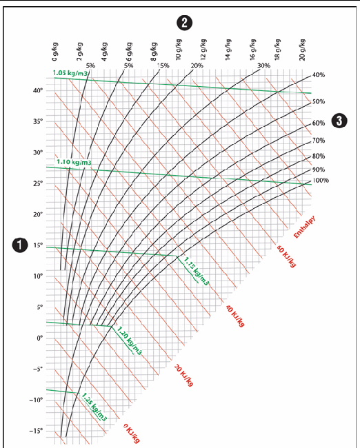
can be used for determining the dew point. Choose the temperature and the humidity level (e.g. 25˚C, 50% humidity) and locate that particular point in this chart. Below this point, you can find the 100% humidity level. To the left of that point is the dew-point temperature of the inlet water.
Example: The climate of data center rooms is usually maintained at 72 ˚F (22 ˚C) with 50% relative humidity. The dew point temperature is then approximately 48.2 ˚F (9˚C). In this case, the recommended inlet temperature of the cooling water should be approximately 54 ˚F (12 ˚C).
FIGURE 1-1 Mollier-h-x Diagram for Humid Air--pressure 0.950 bar (537.0 m/10.0˚C.80.0% rF (relative humidity))
Your data center must have the necessary water infrastructure to support the Sun Cooling Door 5200 requirements.
The Sun Cooling Door 5200 requires the following cooling water connection properties:
| Note - For detailed information on how to meet the requirements above, see your site planning guide and/or Sun representative. |
The Sun Cooling Door 5200 must be connected to a chilled water network by two 1" male threaded pipe connections on the inlet and return, located on the lower rear side of the unit. It is possible to have overhead water connections. Refer to Sun Cooling Door 5200 Installation for Overhead Water Source. Connecting the water source to the door must be managed by the customer.
|
|
Caution - Experienced or licensed technicians, as appropriate per local regulations, should perform the installation of the water source. |
If your Sun Cooling Door 5200 will be connected to water lines routed from below the unit, you must allow for flooring space beneath the unit in raised flooring.
The floor tile cut-outs need to be prepared for the rack/chassis as follows:

When installing the Sun Cooling Door 5200 onto a chassis, follow the dimensions outlined by FIGURE 1-3 for planning rows of racks greater than one rack wide.

|
Server chassis (Sun Blade 6048 Chassis is 606.5 mm in width) |
|
| Note - The above configuration is recommended. This diagram applies to 600mm x 600mm tile configuration. |
Begin the placement of the first rack at the right side of the last tile. The space between the cut-out and the edge of the tile increases with each tile, right to left: The first cut for the first chassis on the right is 69mm from the edge of the tile, for the second tile it is 75.5mm, and for the third tile it is 82mm. Follow this position strategy for each additional rack.
| Note - Tile cut-outs for cable management might need to be considered and are not included in both sketches above. |
| Note - There should be enough space available at the rear of the rack to allow for the installation of the Sun Cooling Door 5200 as well as for opening the door after installation. |
| Sun Cooling Door 5200 Installation and User’s Guide | 820-7182-11 |
Copyright © 2009 Sun Microsystems, Inc. All rights reserved.