| Sun Netra CP32x0 SAS Storage Advanced Rear Transition Module HD User’s Guide |
| C H A P T E R 2 |
|
Installation and Service |
This chapter contains the procedures for installing and removing the Sun Netra CP32x0 SAS Storage Advanced Rear Transition Module HD (ARTM-HD).
This chapter contains the following sections:
The ARTM-HD can be installed into an ATCA shelf (chassis) for front and rear board installations (FIGURE 2-1). The module must be installed in the slot directly behind the Sun Netra ATCA node blade server. These back-to-back slots have common pins to enable passing of signals.
| Note - Connectors on previous blade servers do not mate with connectors on the ARTM-HD. |
Before installing the ARTM-HD, verify the module’s part number to ensure that the correct ARTM-HD is being installed into the system. For information on identifying the ARTM-HD, see Part Number, Serial Number, and FC Address Labels.

|
Caution - Use the ARTM-HD only with compatible blade servers. Attempts to install the ARTM-HD with an incompatible blade server might cause damage to themselves and the blade server. |
FIGURE 2-1 Installing the Blade Server and ARTM-HD Into the ATCA Shelf

The ARTM-HD must be used with a Sun Netra ATCA node blade server for rear I/O access. The ARTM-HD enables access to the network, to a boot device, and to a console terminal.
| Note - The ARTM-HD and the corresponding Sun Netrablade server can be installed while the shelf is powered--however, start with a powered shelf only if you must do so. |
| Note - Optimally, install the ARTM-HD before installing the corresponding Sun Netrablade server. This order ensures proper bring up of the ARTM-HD firmware. |
1. Verify that you have taken the necessary antistatic precautions.
2. Go to the back of the system and choose an appropriate slot for the ARTM-HD.
ARTMs must be installed inline behind the accompanying blade server. For example, if the accompanying blade server is going to be installed in
slot 3, its ARTM must be installed at the back of the system in slot 3.
3. Remove the slot filler panel from the selected blade server slot, if necessary.
4. Prepare the module by loosening the locking screws and opening the injector/ejector latch at the top of the module (FIGURE 2-2).
FIGURE 2-2 Injector/Ejector Latch and Locking Screw

5. Hold the bottom disk cage with one hand and top injector/ejector latch with the other hand, as shown in FIGURE 2-3.
| Note - The following steps apply regardless of how many ARTMs are in the chassis, as long as there is an available slot for the ARTM you are installing. |
FIGURE 2-3 Holding the ARTM-HD During Installation

6. Carefully align the top and bottom edges of the module with the guides in the appropriate slot.
It might be helpful to look into the enclosure to verify correct alignment of the rails in the guides.
7. Taking care to keep the module aligned in the guides, carefully insert the module by simultaneously pressing the bottom disk cage and top injector/ejector latch, which is extended fully open.
FIGURE 2-4 Inserting the ARTM-HD

8. Slide the module in as far as possible and while maintaining pressure on the bottom disk cage, rotate the injector/ejector latch inward to its closed position to fully seat the module in the slot.
9. Tighten the module retention screws to ensure that the module is secured into the shelf.
10. Install the blade server into the front of the shelf (FIGURE 2-1) and push the blade server toward the midplane. Ensure that it is seated properly and that the connectors make good contact with the ARTM-HD.
For further details on installation of the blade server, refer to the appropriate user documentation for the blade server.
If the module is inserted properly, the hotswap switch is activated. The blue Hot-swap LED will blink, then the green OK LED lights.
11. Install the supported peripheral devices at the ARTM-HD connector ports, as required.
Use shielded cables for the ports on the ARTM-HD; the shield should be grounded at both ends. For further details on installation, refer to the appropriate user documentation.
12. Power on the system, if necessary.
Refer to your system manual for instructions on correctly powering on the system.
1. Shut down any operating system accessing the ARTM-HD or its companion blade server.
2. Power off the ARTM-HD from the shelf manager.
For example, to power down just the ARTM-HD in slot 1, log in to the shelf manager and type:
where 9a is the IPMB address for slot 1, and 3 is the FRU number of the ARTM-HD in slot 1.
Alternately, to power down both the ARTM-HD and its companion blade server, type:
3. Loosen the locking screws on the ARTM-HD.
4. Unlatch the top injector/ejector latch and wait for the blue Hot-swap LED to light and stay on solid.
Depending upon the status and functionality of the front blade server, the ARTM-HD blue Hot-swap LED will either blink or go to solid state.
| Note - The following steps apply regardless of how many ARTMs are in the chassis. It might be a little more difficult to grasp an ARTM when the chassis is full. |
5. Remove the module by simultaneously pulling on the the bottom disk cage with one hand and the top injector/ejector latch with the other hand, as shown in FIGURE 2-5.
FIGURE 2-5 Removing the ARTM-HD

6. If the slot is to remain empty, install a filler panel in the slot.
7. Reinstall the blade server, if necessary.ARTM-HD
1. Open the HD latch by pressing the button on the face of the drive.
2. Insert the drive into the appropriate drive bay until the latch closes and the drive fully engages with the connectors.
1. Unmount any file systems using the HD.
2. Locate the drive to be replaced.
If a drive is faulty, the amber fault LED will light.
3. Press the button on the face of the HD to release the latch.
4. Grab the latch and remove the HD from the drive bay.
5. If the slot is to remain empty, install a filler panel in the slot.
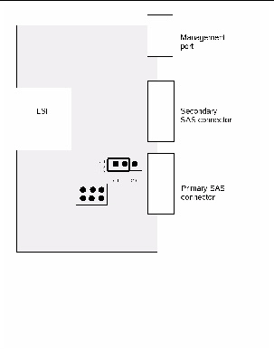
The color of the Out-of-service (OOS) LED can be set to red or amber by moving jumper JU1 to the appropriate position. Setting the jumper to the P1/P2 position makes the OOS LED appear red. Setting the jumper to the P2/P3 position makes the OOS LED appear amber. Amber (position P2/P3) is the default setting for the OOS LED.
1. Remove the ARTM-HD from the chassis.
See Removing the ARTM-HD.
2. Locate jumper JU1 on the board.
JU1 is located next to the Primary SAS connector.
FIGURE 2-6 Jumper setting for red OOS LED (P1/P2)

3. Set the jumper housing to the appropriate setting; P1/P2 for red, P2/P3 for amber.
FIGURE 2-7 Jumper setting for amber OOS LED (P2/P3)

| Sun Netra CP32x0 SAS Storage Advanced Rear Transition Module HD User’s Guide | 820-3147-13 |
Copyright © 2010, Oracle and/or its affiliates. All rights reserved.