| C H A P T E R 1 |
|
Overview |
This chapter provides an overview of the features, configurations, and system requirements of the Sun Netra CP32x0 SAS Storage Advanced Rear Transition Module HD (ARTM-HD).
This chapter contains the following sections:
The Sun Netra CP32x0 SAS Storage Advanced Rear Transition Module HD (ARTM-HD) is a fully compatible, carrier-grade Advanced Telecom Computing Architecture® (ATCA) ARTM for ATCA blade servers designed to be compatible with the AdvancedRTM specification. The ARTM-HD is not compatible with ATCA cards that do not comply with this specification.
The 6 rack unit (6U) form factor, single-slot ARTM supplies single or dual SAS hard disk drives, and rear I/O connections that support additional peripherals for use with compatible ATCA blade servers and external storage arrays. The rear I/O access enables you to replace the ATCA blade servers without disconnecting cables. Industry-standard connectors and pin assignments ensure ease of use and flexible design. The ARTM-HD permits the creation of high-density systems by enabling easy access to I/O (FIGURE 1-1).
Features of the ARTM-HD include:
The ARTM-HD requires an ATCA shelf (chassis) with a midplane that accommodates front and rear blade server installations. The primary purpose of this module is to provide a single or dual SAS drive and rear access connections to the blade server’s I/O devices.
The ARTM-HD is fully compliant with the PICMG® 2.0 Revision 3.1 specification.
The maximum power dissipation is 25 Watts.
TABLE 1-1 lists the airflow cooling requirements based on a maximum power of 25W, which is the only power level available on this ARTM-HD.
TABLE 1-2 lists the pressure drop rates for the ARTM-HD.
FIGURE 1-1 Sun Netra CP32x0 ARTM-HD Components

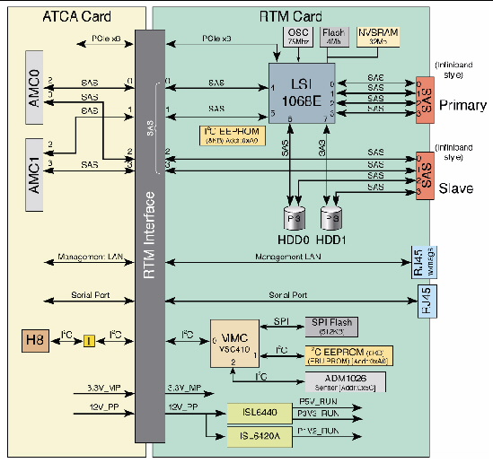
The ARTM-HD installs into the rear of the ATCA enclosure, opposite an ATCA blade server. The ARTM-HD connects to the blade server’s Zone 3 rear connectors. The ARTM-HD carries one serial port, one 10/100/1000 MBASE-T management port (RJ-45), and two external SAS ports to its faceplate (FIGURE 1-1).
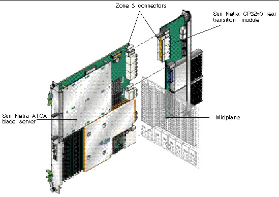
FIGURE 1-3 shows the physical relationship between the blade server, ARTM-HD, and the midplane in a typical ATCA system.
FIGURE 1-3 Relationship of the Blade Server, ATCA Midplane, and ARTM-HD
| Note - When the ARTM-HD is used with a Sun Netra ATCA blade server, shielded cables are required for serial I/O ports. The shields for all shielded cables must be terminated on both ends. |

|
Caution - You must use shielded cables for all ports to satisfy EMI compliance standards. |

The customer can order the ARTM-HD, build a custom module that is ACTA or ARTM compatible, or buy a module from an IHV. A minimum set of I/O is required to provide a boot path for the host blade server and for console I/O to issue commands and read board and system status.
Possible boot and console configurations are described in TABLE 1-3. Sun Microsystems provides the Sun Netra ATCA blade servers and compatible ARTM-HD. This module provides one 10/100/100 MBASE-T Ethernet RJ-45 port and one serial port from the host to the back of the system, and can optionally be used for network booting as a diskless client. The other configurations require IHV hardware.
|
Sun Netra CP32x0 SAS Storage Advanced Rear Transition Module HD (ARTM-HD) (supplied as an option for rear access) |
The Management Ethernet port must be enabled as a boot device in the BIOS before it can be used; the board can run in a diskless client configuration. |
|
|
Sun Netra CP32x0 SAS Storage Advanced Rear Transition Module HD (ARTM-HD) |
||
|
Sun Netra CP32x0 SAS Storage Advanced Rear Transition Module HD (ARTM-HD) |
The Serial port on the front panel provides the path of the default console I/O. When the optional ARTM-HD is installed, the module’s serial port becomes the path of the default console I/O (see FIGURE 1-1 for location). |
The ARTM-HD supports up to two SAS hard disk drives (HDs), with various options. When you order the product, choose the part number corresponding to the capacity (in gigabytes) that you want in either single or dual HDs.
Each HD has the following features:
The ARTM-HD includes an LSI SAS 1068e hard disk drive controller with the following features:
The ARTM-HD includes two external SAS connectors. These connectors can be used to connect additional disk packs, or to create redundancy between two ARTM-HDs and their associated blade servers.
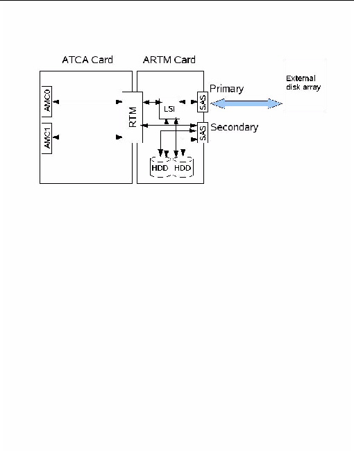
When connecting the ARTM-HD to an external disk array, use the Primary SAS port connector.
FIGURE 1-4 Connecting to an External Disk Array
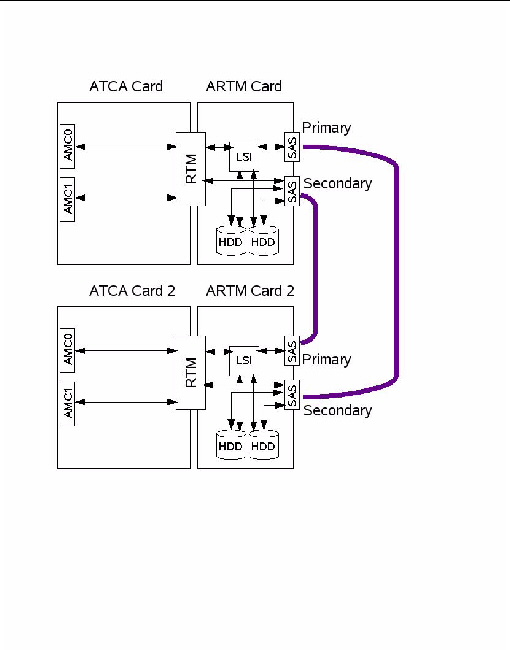
When connecting to another ARTM-HD for redundancy, route the Primary port on each ARTM-HD to the Secondary port on the other ARTM-HD.
FIGURE 1-5 Connecting to Another ARTM
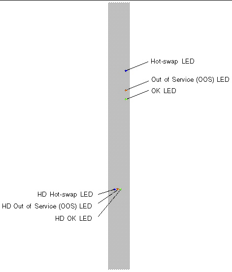
LEDs are located on the panel of the ARTM-HD and on the hard disk drive(s).
The ARTM-HD supports ATCA blade servers designed to be compatible with the AdvancedRTM specification, and the software supported by those blade servers. Refer to the following documentation for software support information:
The ARTM-HD serial number, part number, FibreChannel (FC) address are printed on stickers located on the module. For proper identification of the ARTM-HD, find the Sun Microsystems barcode labels on the module. The barcode labels provide the following information:
FIGURE 1-7 ARTM-HD Identification Labels
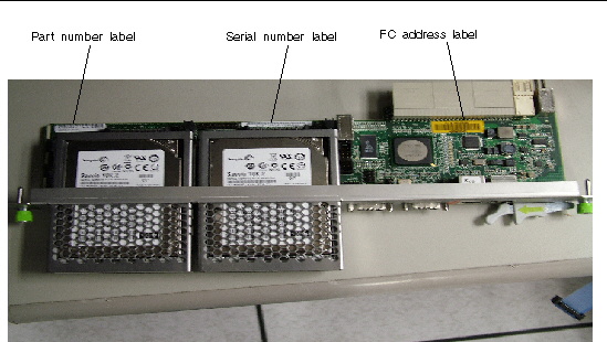
| Note - The illustration shows a sample of the labels for a 146GB ARTM-HD. If your ARTM-HD has a different capacity, the labels show it. |
Copyright © 2010, Oracle and/or its affiliates. All rights reserved.