| Sun Dual 10GbE XFP PCIe ExpressModule User’s Guide |
| C H A P T E R 3 |
|
Installing the ExpressModule |
This chapter describes how to install the Sun Dual 10GbE XFP PCIe ExpressModule in your system and verify that it has been installed correctly.
This chapter contains the following section:
| Note - If you are installing the Sun Dual 10GbE XFP PCIe ExpressModule into a machine running Solaris 10 software, you must install the software before you install the hardware. |
The Sun Dual 10GbE XFP PCIe ExpressModule requires an optical transceiver in at least one port to create an Ethernet connection. The short-range optical transceiver (part number X5558A) and the long-range optical transceiver (part number X5560A-z) are both available from Sun Microsystems.
| Note - Install the optical transceivers into the ExpressModule before installing the ExpressModule into the system. |
|
1. Pull the locking handle into the full horizontal position.
You will feel the handle click into position when it is fully opened.
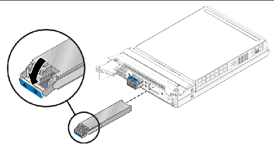
2. Holding the optical transceiver by the edges, align the transceiver with the slot in the ExpressModule and slide the transceiver into the opening.
3. Applying even pressure at both corners of the transceiver, push the transceiver until it is firmly seated in the slot.
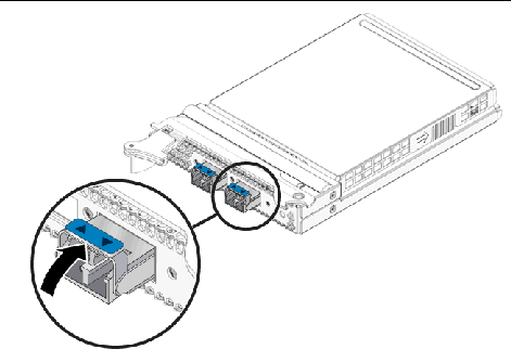
4. Push the handle closed to lock the optical transceiver in place.
5. Repeat Step 1 through Step 4 to install the second optical transceiver
The following instructions describe the basic tasks required to install the ExpressModule. Refer to your system installation or service manual for detailed ExpressModule installation instructions.
| Note - To maintain proper cooling for the ExpressModule in your chassis, all ExpressModule slots must be filled with either operating ExpressModules or filler panels. |
|
1. Halt and power off your system.
2. Power off all peripherals connected to your system.
3. Attach the adhesive copper strip of the antistatic wrist strap to the metal casing of the power supply. Wrap the other end twice around your wrist, with the adhesive side against your skin.
4. Remove the filler panel from the ExpressModule opening.
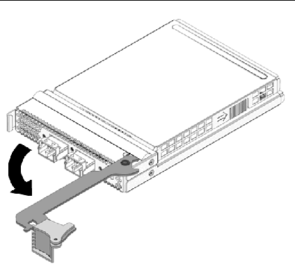
5. Open the latch on the ExpressModule.

6. Align the ExpressModule with the vacant ExpressModule slot (1).
Ensure that the ExpressModule’s indicator lights on the front panel are facing toward you and that the ExpressModule ejector lever on the bottom is fully opened.
7. Slide the ExpressModule into the vacant ExpressModule chassis slot until the ejector lever engages and starts to close (2).
Failure to align the ExpressModule correctly can result in damage with the ExpressModule’s internal connection to the chassis midplane.
8. Complete the installation by closing the ejector lever until the latch snaps into place (3).
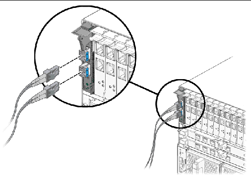
10. Connect the Ethernet cables.
After you install the Sun Dual 10GbE XFP PCIe ExpressModule, but before you power on your system, perform the following tasks to verify the installation. Refer to the Solaris documentation for the detailed instructions.
| Note - Verification is not required if your system supports dynamic reconfiguration (DR). Verification is not supported if your system is running Solaris x86 software. |
|
1. Power on the system, and when the banner appears, press the Stop-A key sequence to interrupt the boot process and display the OpenBoot (ok) prompt.
2. List the network devices on your system.
Checking the .properties output for each device is the surest way to identify the device. Usually /pci@7c0/pci@0/pci@8 or /pci@7c0/pci@0/pci@9 correspond to PCIe slots, so look at those devices first.
| Note - If you do not see the device listed, check that the ExpressModule is properly seated. If necessary, reinstall the ExpressModule (see the appropriate directions in Installing the ExpressModule and following.) |
3. View the device that you installed.
Using the Step 2 example, type:
4. Use the .properties command to display a list of device properties.
The .properties command displays the specific information about the device. For this ExpressModule, your output will be similar to the following:
5. Type the following when you finish looking at the .properties values:
|
 After verifying the ExpressModule installation, perform a reconfiguration boot on your system. Type the following:
| Sun Dual 10GbE XFP PCIe ExpressModule User’s Guide | 820-1606-12 |
Copyright © 2008 Sun Microsystems, Inc. All Rights Reserved.
 To Install an Optical Transceiver
