|
|
| Sun ONE Connector Builder 2.0 Developer's Guide |
Creating the Resource AdapterThis module describes the following topics:
- Mounting the EIS API
- Defining the Resource Adapter
- Generating the Resource Adapter
- Understanding the Resource Adapter Directory Structure
- How the Resource Adapter is Displayed in the IDE
Mounting the EIS API
You need to mount the package containing any EIS API class that you want to use in the IDE.
The EIS Java API must be mounted correctly in the IDE file system. The EIS API can be in the form of a .jar, .class or .java file of a class or interface of the EIS API.
You need to mount the package containing any EIS API class that you want to use in the IDE.
There are two ways to mount an EIS API:
- via the File menu
- via the Explorer area of the IDE
To correctly mount a Java class, select the parent directory of the package you wish to mount. For example, if a class named COTSAPI is located in a physical directory called <connector_builder_install_root>/samples/cots/eissystem/src/com/sun/appinteg/samples/eis and the COTSAPI class' package name is com.sun.appinteg.samples.eis - the directory must be mounted through <connector_builder_install_root>/samples/cots/eissystem/src.
Defining the Resource Adapter
The Connector Builder Wizard is used to define the resource adapter.
The process consists of the following nine steps:
- Step 1 - Template Chooser
- Step 2 - Specifying Adapter Location Information
- Step 3 - Entering Adapter General Information
- Step 4 - Mapping the EIS API
- Step 5 - Customizing Interaction Specs
- Step 6 - Specifying Configuration Properties
- Step 7 - Choosing Authentication and Transactional Support
- Step 8 - Enter Licensing Information
- Step 9 - Set Adapter Icons
You can enter a minimal amount of information on the first panel, generate a complete resource adapter, and then modify the information later via property sheets.
There are two ways to run the Connector Builder Wizard:
- via the IDE
- via the File menu
Step 1 - Template Chooser
From the IDE main menu
- Select File > New. The following screen is displayed.
Choose Template Page
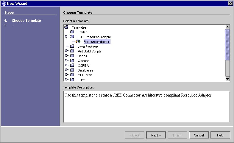
- From the list of templates displayed, select J2EE Resource Adapter > Resource Adapter.
- Click Next.
or
From the IDE Explorer Area
- In the IDE Explorer, select the folder where you want to generate the resource adapter and right-click.
- Select New > J2EE Resource Adapter > ResourceAdapter from the pop up menu.
The Adapter Location Information Page is displayed.
Note The Wizard uses the currently selected directory in the folder as the default location for the generated adapter files. You can change this default while running the Wizard as explained in Step 2 - Specifying Adapter Location Information.
Step 2 - Specifying Adapter Location Information
- Enter the Adapter Logical Name.
This field is required. The Adapter Logical Name cannot contain spaces. The Adapter Logical Name is also used to create the names of classes and files in the generated adapter. After you specify the adapter logical name field and press tab, the Wizard checks that the logical name is correct and unique in the specified directory. If both conditions are met, the Next button is enabled.
- Browse to select the directory where you want the adapter files to be generated.
The directory field has a default value, based on the directory currently selected in the IDE Explorer. This field can be modified using the Browse button. The adapter files are generated in a folder named <Adapter Logical Name> created within this directory. You cannot have two adapters with the same logical name in the same directory.
Adapter Location Information Page
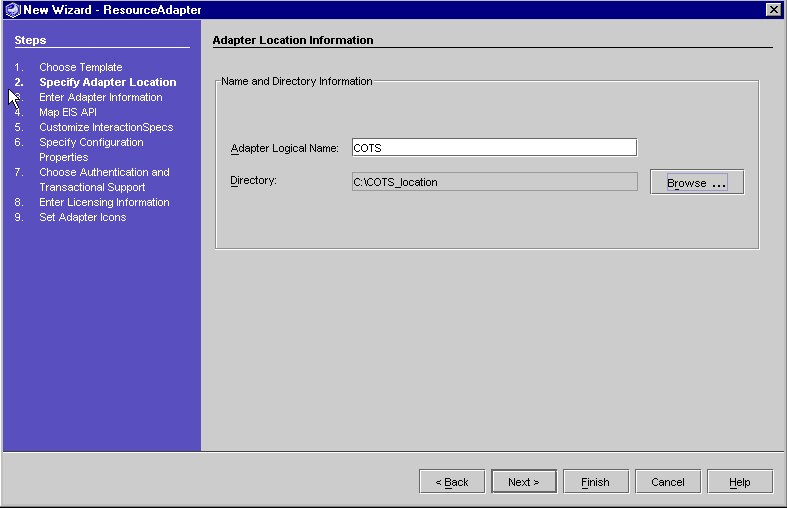
- Click Next. The "Adapter General Information Page" is displayed.
Step 3 - Entering Adapter General Information
The Wizard uses the Adapter Logical Name entered on the Adapter Location Information page to create defaults for the required fields.
- Adapter Name
- Adapter Package (converts upper case letter to lower case)
- EIS Name
- Enter information for all other fields (optional fields).
The Wizard creates default values of 1.0 for the Adapter Version and EIS Version.
You can modify any field in the Adapter General Information page.
Adapter General Information Page
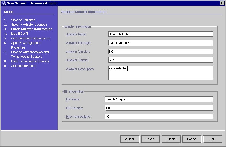
The following table lists the fields in the Adapter. The left-hand column lists the field name and the right-hand column provides a description.
- Click Next. The "Initial Adapter EIS API Mapping Page" is displayed.
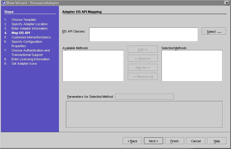
Step 4 - Mapping the EIS API
- In the "Initial Adapter EIS API Mapping Page", click Select and navigate to the EIS API. See "Selecting a Class of the EIS API".
Initial Adapter EIS API Mapping Page
Selecting a Class of the EIS API
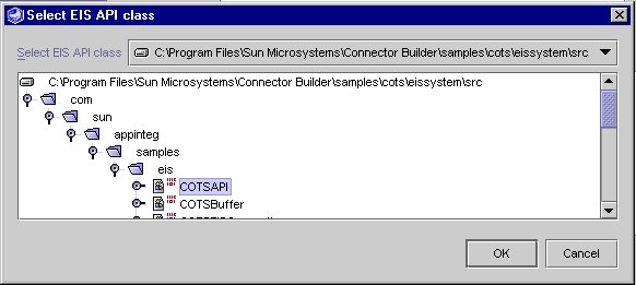
- Select the .java or .class file of a class or interface of the EIS API.
- Repeat steps 1 and 2 to add additional files or interfaces.
- Click OK.
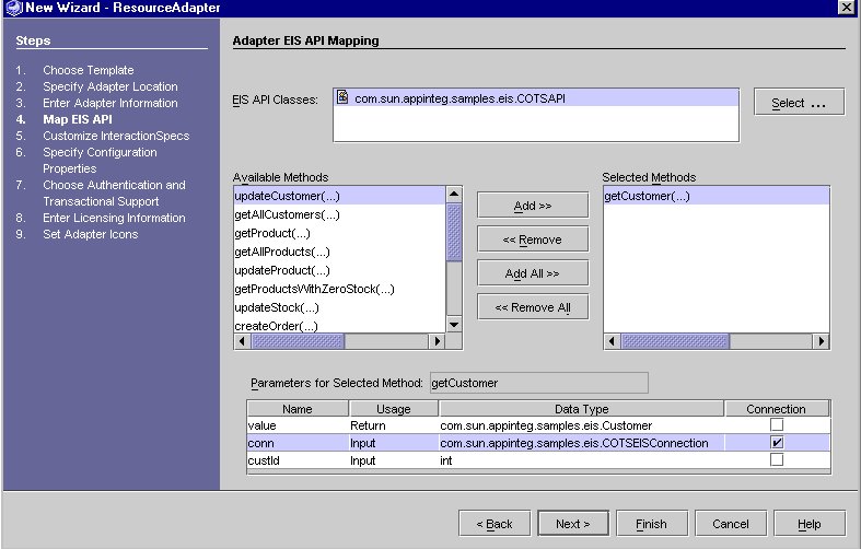
The class' public methods are displayed in the Available Methods as shown in the following screen.
Adapter EIS API Mapping Information Screen

- The methods of the EIS API that are to be exposed via the Adapter need to be added to the Selected Methods.
Select one or more methods in the Available Methods and use Add to move methods to the Selected Methods or select Add All to move all the methods. To remove methods from the Selected Methods, select the method or methods and click Remove or select Remove All to move all the methods back to the Available Methods.
- Highlight a Selected method. The Parameters for Selected Method table displays the parameters. The information displayed for each parameter includes:
- Name - must be a valid Java identifier. Each name within the same method must be unique.
- Usage - displays whether the parameter is the method's return value or an input parameter.
- Data Type - the datatype of the parameter.
- Connection - Must be an input parameter of type class. Only one connection per method is allowed. You cannot specify Primitive and Array data types as connections.
Name and Connection are the only editable columns.
Identifying Connection Objects
Many EIS APIs use a Java object to represent information about the physical connection between the Java application and the EIS. The EIS API documentation might refer to these objects as a "context" object, a connection object, or some other name. Often, one method in the EIS API accepts a username and password as parameters and, if they are valid in the EIS, return a connection object representing the newly-established physical link to the EIS. Other methods in the API accept this connection as a parameter along with other parameters specific to that method's purpose.
The Connector Builder run-time system and the container in which the resource adapter runs optimize the use of physical connections and enforce security for them. It is important that Java applications that use Connector Builder resource adapters be prevented from manipulating these connection objects yet some of the EIS API methods require the connection object as a parameter.
The Connector Builder handles this situation by providing special treatment for parameters that are connection objects. For these parameters, the Connector Builder generates code that automatically retrieves that connection object from inside the resource adapter and passes it to the EIS API method. The application neither receives nor provides the connection object itself.
Note This step must be repeated for each Connection Object in each method in the EIS API.
To Specify Connection Parameters to Connector Builder
- Select the method that is to be customized in the Selected Methods.
The method's parameters are displayed in the Parameters table.
- For each parameter which is a connection object, select the Connection checkbox as shown in the following screen.
Customize Parameter
Step 5 - Customizing Interaction Specs
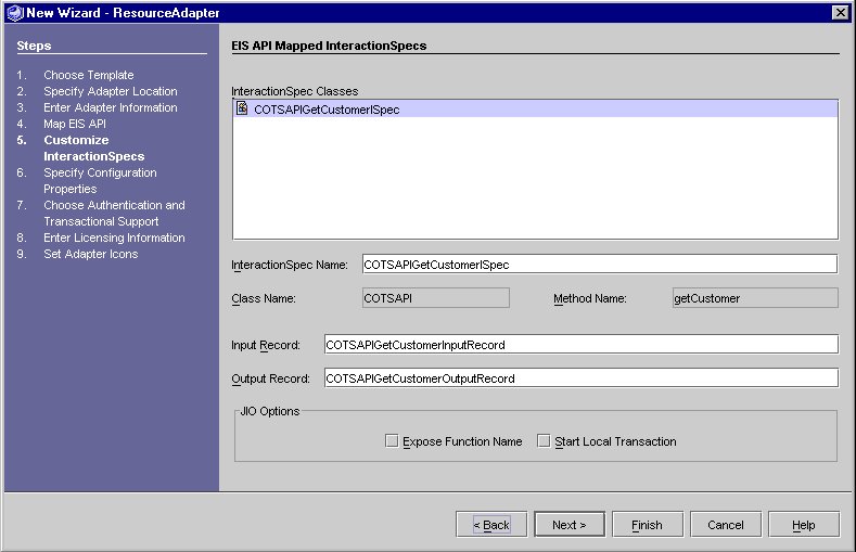
For each EIS API method selected, Connector Builder generates a corresponding InteractionSpec class, as described in the J2EE Connector Architecture. An InteractionSpec represents the way an EIS API method can be called from a resource adapter. An application that uses the CCI programming model can establish a connection to the EIS and then use InteractionSpec objects to invoke methods in the EIS API. The Connector Builder Wizard allows you to modify the names of these classes using the following screen.
EIS API Mapped Interaction Specs
As a further convenience, Connector Builder also generates a Java Interaction Object (JIO) with each generated InteractionSpec. The application can use a JIO simply and easily to invoke the corresponding EIS API method. The JIO automatically obtains a connection to the EIS if necessary and start a transaction in the EIS before invoking the method. In addition, the JIO can accept an additional parameter - the name of a function to be performed - which allows the JIO to be used with general-purpose EIS API methods.
The InteractionSpec classes list displays the names of the InteractionSpec classes that are generated for the Selected methods from the previous panel.
When you highlight an item in the list, the fields in the panel display the relevant information for that InteractionSpec. The InteractionSpec Name, Input Record and Output Record are required for each InteractionSpec. They can be modified but must contain only valid Java identifiers and must be unique.
The Output Record is a class that corresponds the return value for the method that the InteractionSpec class is based on. The Input record corresponds to the input parameters for the method.
Validations are performed when you exit each field.
There are two types of customizations you might choose to make to an InteractionSpec:
Change the Name of the InteractionSpec and Records
The InteractionSpec Name defaults to <className><methodName>ISpec. InteractionSpec names must be unique. For overloaded methods, each variation of the method must have a unique InteractionSpec name.
To Change the Name of the InteractionSpec
- Select an InteractionSpec class from the list displayed in "EIS API Mapped Interaction Specs".
- Change the name of the InteractionSpec.
To Change the Name of the Input and Output Record
- Select the Input or Output Record displayed in "EIS API Mapped Interaction Specs".
- Change the name of the Record
Set JIO Options
To Customize JIO Options for the Interaction Spec
- Select an InteractionSpec from the list displayed in "EIS API Mapped Interaction Specs".
You can set the Expose Function Name and Start Local Transaction properties (optional). Choose Expose Function Name if the corresponding EIS API method is a general-purpose method which accepts the name of a function to execute as a parameter. Choose Start Local Transaction if you want every use of this JIO to automatically start a local transaction using the EIS API's transaction features.
- Click Next when you have finished.
Step 6 - Specifying Configuration Properties
The configuration properties are used at run-time to create a connection with the EIS. The J2EE Connector Architecture specification describes two types of configuration properties. A property of the first type has a value that applies to all physical connections to a given EIS, regardless of the client that needs to use the physical connection. Common examples of this type of property include a URL, or host name and port number. The resource adapter always connects to the configured URL (or host and port number) to establish physical links to the EIS.
In contrast, the value of a property of the second type can change from one client's request for a physical connection to the next. Connections to a single EIS on behalf of two different users, for instance, would use different username and password values but the same URL value. The Connector Builder considers properties in this second category as "client properties." You can specify a value for such a property on the Configuration Properties page (see "Configuration Properties Editor"), but the resource adapter can override that default value at run-time when it requests a connection on behalf of a particular client application.
The Connector Builder generates certain classes differently depending on which properties are client properties and which are not. You indicate which properties should be treated as client properties by marking the Client Can Override checkbox in the Properties Table on the Configuration Parameters page.
Configuration Properties Editor
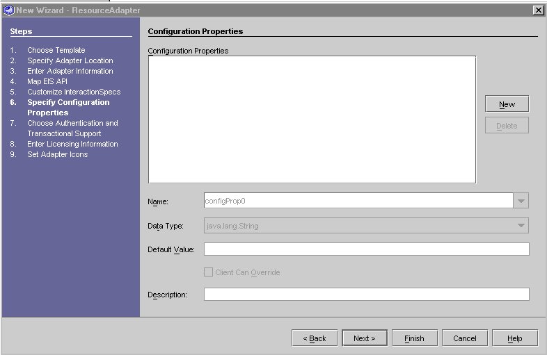
To Edit or Add a Configuration Property
- In the Configuration Properties Editor screen click New.
Configuration Property Editor
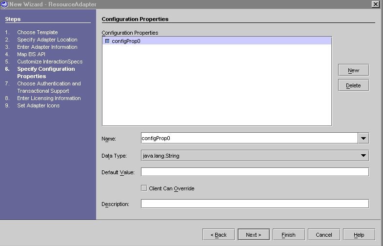
When you click New, the name of a new property appears in the list. By default, the name of the new property is configProp0, configProp1, etc. (depending on how many properties are in your current list).
To remove a property, select the name in the Configuration Properties list and click Delete.
- Fill in the fields as described in the table below.
- Click Next.
The "Configuration Properties" table lists the configuration properties. The left column lists the parameters the right column provides a description.
Step 7 - Choosing Authentication and Transactional Support
The "Authentication and Transactional Support Panel" displays the Authentication and Transactional Support Information page.
- Select the Authentication Mechanism that the adapter will use.
- Basic Password - user-password based authentication mechanism that is specific to an EIS.
- Kerbv5 Credential - Kerbervos version 5 based authentication mechanism.
If you do not select either or both of the check boxes, no authentication method will be used.
Authentication and Transactional Support Panel
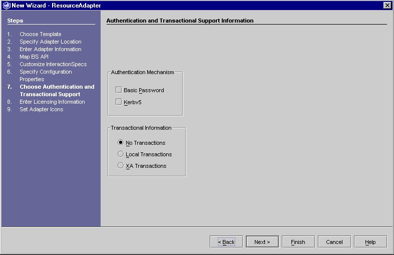
- Select the Transaction Mechanism which the adapter will support.
No Transactions (default) - the resource adapter supports neither Local nor XA Transactions.
Local Transactions - the resource adapter supports transactions that are managed internal to the EIS.
XA Transactions - the resource adapter supports both local transactions that are controlled and coordinated by a transaction manager external to EIS.
- Click Next.
Refer to the J2EE Connector Architecture specification or refer to "J2EE Connector Architecture" for the URL and for additional information.
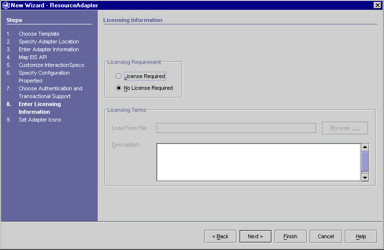
Step 8 - Enter Licensing Information
The "Licensing Panel" is used to collect licensing information about the resource adapter.
- Select the Licensing Mechanism
If you select License Required, enter the License Information manually in the Description area or use the Browse button to import the information from a file.
- Click Next.
Licensing Panel
Step 9 - Set Adapter Icons
The icons are used to represent the generated resource adapter.
The "Set Adapter Icons Panel" displays the icon information.
Set Adapter Icons Panel
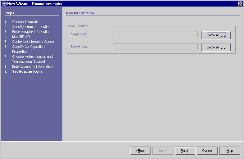
- Click Finish to generate the Resource Adapter.
Generating the Resource Adapter
The resource adapter is generated at this point. When you click Finish, the adapter and JIO generators are invoked. Status messages are displayed in the status text area of the IDE, indicating progress of the adapter generation. The messages displayed are "Generating Adapter...", "Generating Java Interaction Objects ..." and then "Adapter Generation is complete". The IDE output window displays a list of all the files generated and other notes about the generation process. In particular, special notes list mandatory customizations that you must implement to make the generated resource adapter work correctly with your EIS API.
Once the adapter generation is complete, the adapter's root directory (which was specified as the Directory in Step 2 - Specifying Adapter Location Information) is mounted as an IDE filesystem, and appears within the Explorer area of the IDE. If you expand this directory, you can see a "node" (icon and the adapter name) which represents the newly created adapter. The adapter node can also be expanded to show subdirectories of the adapter.
One of these subdirectories is src. After the Sun ONE Connector Builder generates the resource adapter, the src directory contains a text file named adapterGeneration.txt that describes the results of the generation. The file lists the files created and also highlights special steps you should perform - such as certain mandatory customizations to the generated Java code - to complete the resource adapter.
Internationalization Support For Generated Code
Some fields, whose values are in the generated code, do not support internationalization and cannot contain multi-byte characters.
Refer to "Internationalization" for more details.
Understanding the Resource Adapter Directory Structure
The Connector Builder constructs a directory structure for each resource adapter you create. You choose the root directory for this structure on the Adapter Location Information screen of the Connector Builder Wizard. The following screen displays the Generated Resource Adapter Directory.
Generated Resource Adapter Directory
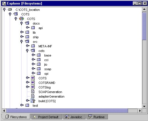
The table below lists the directory structure of the connector. The left most column lists the directory name, the middle columns list the sub-directories and the right most column gives a description of each one.
All subdirectories are created under a main directory named <AdapterLogicalName> which is created within the location specified in the Adapter Location.
Directory Structure
Directory Name
Sub-directories
Description/Contents
docs
for the adapter's API documentation
lib
for native libraries, additional jar files, or other adapter-dependent files the adapter uses at run-time, files in this directory are packaged along with the resource adapter
ext
for native libraries and additional jar files that need to be used during compile time but are not packaged
ship
for the final adapter software
src
contains three generated properties files and the generation report .txt file
META-INF
contains resource adapter deployment descriptor (ra.xml) and Sun ONE App Server resource adapter deployment descriptor (sun-ra.xml).
package
contains a set of subdirectories for the package entered in Step 2 - Specifying Adapter Location Information. For example, if you specify "com.mycompany.someadapter" as the package, the /src directory would contain subdirectories /src/com/mycompany/someadapter.
/base
/cci
generated classes that implement the javax.resource.cci interfaces
/spi
generated classes that implement the javax.resource.spi interfaces
/cci
generated, customizable classes that extend the /base/cci classes
/jio
generated, customizable Java Interaction Object classes
/spi
generated, customizable classes that extend the /base/spi classes
/soap
contains the SOAP services related files for the adapter
/serializers
generated template serializer/deserializer java files. These classes need to be customized to provide marshalling/unmarshalling logic. Refer to "Adding SOAP Services to the Resource Adapter for more information.
/clients
contains service clients for each exposed SOAP service.
/deployment
contains deployment descriptors for each exposed SOAP service
images
contains copies of the .gif. or jpg files specified in the Step 9 - Set Adapter Icons in the Wizard.
test
for the resource tests
config
directory where test client property files are placed.
src
directory where the generated sample test case is placed. User written test cases should be written in this directory.
How the Resource Adapter is Displayed in the IDE
The root directory of each Connector Builder adapter is mounted as an IDE Filesystem when an adapter is generated. This root directory appears within the Explorer area of the IDE. Expanding the adapter's root directory displays the adapter node (icon and adapter name). A number of context-sensitive actions are available for this adapter, and they are visible on a contextual menu which is displayed when you right click on the adapter node.
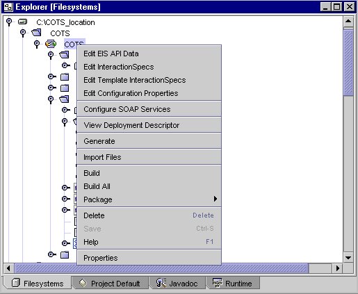
The following table describes the various menu options that you can use with the Connector Builder. The left column describes the menu items, the center column explains the options, and the right column provides a description.
Adapter's Contextual Menu
Menu Item
Option
Description
Edit EIS API data
Selecting this option displays the same panel as is shown in Step 4 - Mapping the EIS API of the Wizard. You can select additional methods of the EIS API classes to be exposed by the adapter, select additional EIS API classes to include in the adapter's list, or remove any previous selections. In addition, you can utilize this panel to change Connection Object information. NOTE: You can also modify EIS API data by selecting the Properties menu option, then clicking on the ... beside the "EIS API Definition" property.)
Edit Interaction Spec
The Interaction specification is the generated Java class that represents each selected EIS API method. It enables a component to execute an interaction with an EIS instance.
Edit Template Interaction Spec
Select this function to allow the user to create Interaction Spec and related classes that are not mapped to the EIS API.
Edit Configuration Properties
Selecting this options displays the Configuration Properties Editor that allow you to add or modify the configuration properties.
Configure SOAP Services
Selecting this option displays the SOAP Layer Editor panel. You can enter the required information, then choose OK when finished. Clicking OK does not automatically save your changes to the definition. You need to invoke the Save context menu option to save the changes or the Generate menu option to save the changes and to re-generate the adapter.
View Deployment Descriptor
Selecting this option opens a read-only view of the generated Deployment Descriptor for the adapter, within the IDE's Source Editor area.
The contents of the deployment descriptor depend on input you provide to the Connector Builder, either through the Wizard when you define the resource adapter or through the property panels when you modify it. You should not directly modify the Deployment Descriptor file.
Generate
Selecting this option regenerates the adapter, using the updated adapter information. If changes had been made to any of the adapter information (either via the Properties option, or the Edit EIS API data option), but not yet saved, selecting Generate saves all modifications before the adapter generator is invoked. Java Interaction Objects are also re-generated at this time. See the Defining SOAP Accessibility Framework Configuration section of this document.
Import Files
Selecting this option displays a panel which allows you to copy files (such as libraries and jar files), which are required by the adapter at run-time, into the lib directory of the adapter's directory structure. These files are then be packaged with the adapter.
Build
Runs the adapter's build script. All adapter classes, as well as user test cases (if they exist) are compiled. The resulting java classes are placed within the adapter's build directory.
This action is equivalent to you expanding the adapter's src directory in the IDE's Explorer area, then double-clicking on the build.xml.
Build All
Equivalent to the Build action, except that any existing compiled source files are deleted first.
Package
Adapter only
Packages the adapter into a .rar file.
Adapter with Tests
Packages the adapter, along with its test cases, into a .rar file.
Adapter with SOAP Services
Packages the adapter, along with its generated SOAP services, into a .rar file.
This menu option is not enabled unless SOAP services have been created for this adapter.
Adapter with SOAP Services and Tests
Packages the adapter, along with its test cases and generated SOAP services, into a .rar file.
This menu option is not enabled unless SOAP services have been created for this adapter.
Delete
Deletes adapter node and all files in the adapter directory structure.
Save
This menu option is only be activated if you have made any changes to the adapter information, via the Properties option or the Edit EIS API data panel. Saves all adapter data changes.
Help
Opens module's online help.
Properties
Opens the Property Sheet editors, which can be used to modify any adapter data. Refer to the section Properties for more details.