| C H A P T E R 2 |
|
Hardware Installation and Removal |
This chapter describes how to install and remove the HBA. Refer to your system installation or service manual for detailed instructions.
This chapter contains the following topics:

|
Caution - Damage to the HBA can occur as the result of careless handling or electrostatic discharge (ESD). Always handle the HBA with care to avoid damage to electrostatic sensitive components. |
To minimize the possibility of ESD-related damage, use both a workstation antistatic mat and an ESD wrist strap. You can get an ESD wrist strap from any reputable electronics store or from Sun as part number #250-1007. Observe the following precautions to avoid ESD-related problems:
Follow the procedures in this section to install the hardware:
|
1. Attach an ESD wrist strap (see Observing ESD and Handling Precautions).
2. Refer to your system installation or service manual to determine an appropriate ExpressModule slot in which to install the HBA.
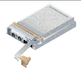
3. Press down the plastic tab to release the ExpressModule latch and pull the lever out until it is nearly perpendicular with the ExpressModule front panel.
FIGURE 2-1 Releasing the HBA Latch

4. Insert the HBA into its slot, being careful that the tooth on the bottom of the lever does not come in contact with the chassis sheet metal during insertion.
5. When the HBA is inserted nearly all the way into its slot, push the lever back into its fully closed position, allowing the lever tooth to insert the HBA fully into place.
|
| Note - The HBA does not allow normal data transmission on an optical link unless it is connected to another similar or compatible Fibre Channel (FC) product (that is, multimode to multimode). |
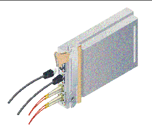
1. Use multimode fiber-optic cable, intended for short-wave lasers, that adheres to the specifications in TABLE 2-1.
2. Connect the fiber-optic cable to an LC connector on the HBA.
3. Connect the other end of the fiber-optic cable to the Fibre Channel device.
4. Connect the Ethernet cable to the Ethernet connector on the HBA.
5. Connect the other end of the Ethernet cable to the Ethernet Device.
FIGURE 2-2 Attaching the Optical Cables

|
After installing the hardware and connecting the cables, you can power on the HBA.
1. Verify that the HBA is securely installed in the system.
2. Verify that the correct optical and Ethernet cables are attached.
3. Refer to your system installation or service manual to determine how to power up the system blade.
4. Watch the Light-Emitting Diodes (LEDs) status for the Power-on Self Test (POST) results as shown in TABLE 2-2, TABLE 2-3, and TABLE 2-4.
This section contains the following topics:
See FIGURE 2-3 to determine the LED locations.
Each port has a corresponding set of LEDs that provide a visual indication of the operating state.

TABLE 2-2 summarizes the Fibre Channel LED indicator combinations (LEDs 1, 2, and 3 in FIGURE 2-3 ).
TABLE 2-3 summarizes the Ethernet LED indicator combinations (LEDs 5 and 7 in FIGURE 2-3).
TABLE 2-4 summarizes the power and attention switch LED combination (LEDs 9 and 10 in FIGURE 2-3).
|
Hot-plug operation is in progress and insertion or removal of the HBA is not permitted. |
|
1. Locate the green Power indicator near the bottom of the HBA front panel (FIGURE 2-3).
See Power and Attention Switch LED Scheme to determine its status.
2. If the green Power indicator is not illuminated, briefly press the Attention button near the bottom of the HBA front panel.
The green power LED will blink for approximately five seconds and then remain on, indicating that the HBA has been properly configured.
3. To cancel the operation, press the button again before it stops blinking.
This section contains the following topics:
|
1. Use the cfgadm command to verify proper ExpressModule installation.
If the HBA is properly installed and connected, you will see output similar to the following.
Ap_Id Type Receptacle Occupant Condition c3 fc connected configured ok c4 fc connected configured ok pcie5 ethern/hp connected configured ok |
2. If the HBA is shown as unconfigured or disconnected, use the cfgadm -c configure command to configure the HBA.
Note - Diagnostic support for the HBA is included in the SunVTS software. The SunVTS software is included with the Solaris 10 s10u4 OS and is also available for download at: http://www.sun.com/oem/products/vts software. The SunVTS software is included with the Solaris 10 s10u4 OS and is also available for download at: http://www.sun.com/oem/products/vts
|
|
If the HBA has been installed correctly, the Windows OS detects the device and displays the Found New Hardware window. The Found New Hardware wizard will launch.
| Note - Leave the Found New Hardware wizard window open, and then load the Fibre Channel and Ethernet drivers, as described in Installing Software for the Windows OS. |
|
If the HBA has been installed correctly, you will see the following line in the /var/log/vmkernel file:
The following instructions describe the tasks required to remove the HBA. Refer to your system installation or service manual for detailed HBA removal instructions.
The following steps summarize the hardware removal process:
1. Either halt the operating system and remove power from the server blade, or prepare the HBA for hot-plug removal with one of the following:
|
1. Press and release the Attention button near the bottom of the HBA front panel (FIGURE 2-3).
The Attention LED near the button will blink for approximately five seconds, indicating that the HBA is being prepared for removal.
2. If you want to stop the operation, press the button again before the LED stops blinking.
3. When the LED stops blinking and goes dark, you can remove the HBA.
|
If you want to remove the HBA without first halting the operating system and removing power from the associated server blade, you can prepare it for removal as follows:
1. Use the cfgadm command to identify the HBA to be removed.
Ap_Id Type Receptacle Occupant Condition pcie5 ether/hp connected configured ok pcie6 ether/hp connected configured ok |
2. Use the ifconfig command to identify the Ethernet ports on the HBA to be disconnected.
e1000g5: flags=201000803<UP,BROADCAST,MULTICAST,IPv4,CoS> mtu 1500 index 6 inet 200.17.188.224 netmask ffffff00 broadcast 200.17.188.255 ether 0:c0:dd:9:a9:7b |
3. Use the unplumb command to disconnect the Ethernet ports on the HBA.
4. Use the cfgadm -c unconfigure command to unconfigure the attachment point ID (Ap_Id) for the HBA.
5. Use the cfgadm -c disconnect command to prepare the HBA for removal.
A blinking Power indicator LED indicates that the HBA is being prepared for removal. A dark Power indicator LED indicates that the HBA is ready to be removed.
|
 Use an ESD strap, depress the ExpressModule latch to disengage the HBA, and then pull forward and down to dislodge it. You can now remove the HBA.
Copyright © 2008, Sun Microsystems, Inc. All Rights Reserved.