| Skip Navigation Links | |
| Exit Print View | |

|
Sun SPARC Enterprise T5140 and T5240 Servers Topic Set |


Documentation, Support, and Training
Sun SPARC Enterprise T5140 and T5240 Servers Site Planning Guide
Minimum Clearance for Service Access
Agency Compliance Specifications
Operating Environment Requirements
Input Power Information and Precautions
Optional Component Installation
Configure the Service Processor
Cabling Notes for Both Servers
Port, Connector, and LED Locations for Both Servers
Slide Rail Assembly Notes for Both Servers
Cable Management Notes for Both Servers
Installing the Sun SPARC Enterprise T5140 and T5240 Servers
Installing the Servers in a Rack
Installing the Cable Management Arm for Both Servers
Connecting the Server Cables for Both Servers
Powering On the System for the First Time
Enable the Service Processor Network Management Port
Logging Into the Service Processor
Using the Service Processor for Common Operations
Booting the Solaris Operating System
Verifying System Functionality
Boot Device Selection Overview
Installing the Servers With the Express Rail Rackmounting Kit
Slide Rail Assembly Notes for the Express Rail Rackmounting Kit
Install the Slide Rail Assemblies
Insert and Lock the Server in the Rack
Assembling and Installing DC Power Cables for the Sun SPARC Enterprise T5140 Server
Requirements for Servers With DC Input Power
DC Supply and Ground Conductor Requirements
Overcurrent Protection Requirements
Assembling and Installing the DC Input Power Cables
Assembling and Installing DC Power Cables for the Sun SPARC Enterprise T5240 Server
Requirements for Servers With DC Input Power
DC Supply and Ground Conductor Requirements
Overcurrent Protection Requirements
Assembling and Installing the DC Input Power Cables
Creating Hardware RAID Volumes
Devices and Device Identifiers
Sun SPARC Enterprise T5x40 Device Tree
Managing Logical Domains Software
OpenBoot Configuration Variables
OpenBoot Configuration Variables on the SCC
Understanding ILOM for the Sun SPARC Enterprise T5140 and T5240 Servers
Platform-Specific ILOM Features
Viewing and Configuring Host Control Information
Managing System User Interactions
Managing the Service Processor
Change Console Escape Characters (CLI)
Changing Configuration Policy Settings
Specify Host Behavior With the Virtual Keyswitch
Specify Host Behavior With the Virtual Keyswitch (Web Interface)
Discover IPMI Sensors and Indicators
Sensors on Sun SPARC Enterprise T5140 and T5240 Servers
Indicators on the Sun SPARC Enterprise T5140 and T5240 Servers
Discover ALOM Compatibility Information
Event Messages Available Through the ALOM Compatibility Shell
Infrastructure Boards in Sun SPARC Enterprise T5140 Servers
Infrastructure Boards in Sun SPARC Enterprise T5240 Servers
Internal System Cables for Sun SPARC Enterprise T5140 Servers
Internal System Cables for Sun SPARC Enterprise T5240 Servers
Rear Panel Components and Indicators on Sun SPARC Enterprise T5140 Servers
Front Panel Controls and Indicators on Sun SPARC Enterprise T5240 Servers
Rear Panel Components and Indicators on Sun SPARC Enterprise T5240 Servers
Status LEDs for Ethernet Ports and the Network Management Port
Diagnostics Tools Quick Reference
Managing Faults Using the PSH Feature
Managing Components With Automatic System Recovery Commands
Detecting Faults Using SunVTS Software
Preparing to Service the System
Find the Chassis Serial Number
Removing Power From the System
Positioning the System for Servicing
Four-Drive Capable Backplane Configuration Reference
Eight-Drive Capable Backplane Configuration Reference
Sixteen-Drive Capable Backplane Configuration Reference
Servicing Motherboard Components
Servicing the Memory Mezzanine Assembly (Sun SPARC Enterprise T5240)
Servicing the Motherboard Assembly
Power Supply Configuration Reference
Servicing Boards and Components
Servicing the Hard Drive Backplane
Servicing Front Control Panel Light Pipe Assemblies
Servicing Power Distribution Boards
Servicing Power Supply Backplanes (Sun SPARC Enterprise T5240 Servers)
Returning the Server to Operation
Reinstall the Server in the Rack
Return the Server to the Normal Rack Position
Connect Power Cords to the Server
Power On the Server Using the poweron Command
Power On the Server Using the Front Panel Power Button
Identifying FRUs in Sun SPARC Enterprise T5140 Servers
Motherboard Components in Sun SPARC Enterprise T5140 Servers
I/O Components in Sun SPARC Enterprise T5140 Servers
Power Distribution/Fan Module Components in Sun SPARC Enterprise T5140 Servers
Internal Cables for Onboard SAS Controller Cards in Sun SPARC Enterprise T5140 Servers
Identifying FRUs in Sun SPARC Enterprise T5240 Servers
Motherboard Components in Sun SPARC Enterprise T5240 Servers
Memory Mezzanine Components in Sun SPARC Enterprise T5240 Servers
I/O Components in Sun SPARC Enterprise T5240 Servers
Power Distribution/Fan Module Components in Sun SPARC Enterprise T5240 Servers
Internal Cables for Onboard SAS Controller Cards in Sun SPARC Enterprise T5240 Servers
HDD Data Cable Routing for SAS RAID Controller Cards in Sun SPARC Enterprise T5240 Servers
The following figure shows the layout of the T5140 server front panel, including the power and system locator buttons and the various status and fault LEDs.
Note - The front panel also provides access to internal hard drives, the removable media drive, and the two front USB ports.
Figure 50 Front Panel Controls and Indicators on Sun SPARC Enterprise T5140 Servers
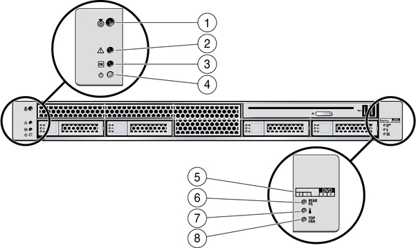
Figure Legend
1 Locator LED and button
2 Service Required LED
3 Power OK LED
4 Power button
5 Hard Drive map
6 Power Supply Service Required LED
7 Overtemp LED
8 Fan Module Service Required LED
The following table provides descriptions of these controls and indicators.
Table 34 Front Panel Controls and Indicators (Sun SPARC Enterprise T5140 and T5240 Servers)
|


|