| Skip Navigation Links | |
| Exit Print View | |

|
Sun SPARC Enterprise T5140 and T5240 Servers Topic Set |


Documentation, Support, and Training
Sun SPARC Enterprise T5140 and T5240 Servers Site Planning Guide
Minimum Clearance for Service Access
Agency Compliance Specifications
Operating Environment Requirements
Input Power Information and Precautions
Optional Component Installation
Configure the Service Processor
Cabling Notes for Both Servers
Port, Connector, and LED Locations for Both Servers
Slide Rail Assembly Notes for Both Servers
Cable Management Notes for Both Servers
Installing the Sun SPARC Enterprise T5140 and T5240 Servers
Installing the Servers in a Rack
Installing the Cable Management Arm for Both Servers
Connecting the Server Cables for Both Servers
Powering On the System for the First Time
Enable the Service Processor Network Management Port
Logging Into the Service Processor
Using the Service Processor for Common Operations
Booting the Solaris Operating System
Verifying System Functionality
Boot Device Selection Overview
Installing the Servers With the Express Rail Rackmounting Kit
Slide Rail Assembly Notes for the Express Rail Rackmounting Kit
Install the Slide Rail Assemblies
Insert and Lock the Server in the Rack
Assembling and Installing DC Power Cables for the Sun SPARC Enterprise T5140 Server
Requirements for Servers With DC Input Power
DC Supply and Ground Conductor Requirements
Overcurrent Protection Requirements
Assembling and Installing the DC Input Power Cables
Assembling and Installing DC Power Cables for the Sun SPARC Enterprise T5240 Server
Requirements for Servers With DC Input Power
DC Supply and Ground Conductor Requirements
Overcurrent Protection Requirements
Assembling and Installing the DC Input Power Cables
Creating Hardware RAID Volumes
Devices and Device Identifiers
Sun SPARC Enterprise T5x40 Device Tree
Managing Logical Domains Software
OpenBoot Configuration Variables
OpenBoot Configuration Variables on the SCC
Understanding ILOM for the Sun SPARC Enterprise T5140 and T5240 Servers
Platform-Specific ILOM Features
Viewing and Configuring Host Control Information
Managing System User Interactions
Managing the Service Processor
Change Console Escape Characters (CLI)
Changing Configuration Policy Settings
Specify Host Behavior With the Virtual Keyswitch
Specify Host Behavior With the Virtual Keyswitch (Web Interface)
Discover IPMI Sensors and Indicators
Sensors on Sun SPARC Enterprise T5140 and T5240 Servers
Indicators on the Sun SPARC Enterprise T5140 and T5240 Servers
Discover ALOM Compatibility Information
Event Messages Available Through the ALOM Compatibility Shell
Infrastructure Boards in Sun SPARC Enterprise T5140 Servers
Infrastructure Boards in Sun SPARC Enterprise T5240 Servers
Internal System Cables for Sun SPARC Enterprise T5140 Servers
Internal System Cables for Sun SPARC Enterprise T5240 Servers
Front Panel Controls and Indicators on Sun SPARC Enterprise T5140 Servers
Rear Panel Components and Indicators on Sun SPARC Enterprise T5140 Servers
Front Panel Controls and Indicators on Sun SPARC Enterprise T5240 Servers
Rear Panel Components and Indicators on Sun SPARC Enterprise T5240 Servers
Status LEDs for Ethernet Ports and the Network Management Port
Diagnostics Tools Quick Reference
Managing Faults Using the PSH Feature
Managing Components With Automatic System Recovery Commands
Detecting Faults Using SunVTS Software
Preparing to Service the System
Find the Chassis Serial Number
Removing Power From the System
Positioning the System for Servicing
Four-Drive Capable Backplane Configuration Reference
Eight-Drive Capable Backplane Configuration Reference
Sixteen-Drive Capable Backplane Configuration Reference
Servicing Motherboard Components
Servicing the Memory Mezzanine Assembly (Sun SPARC Enterprise T5240)
Servicing the Motherboard Assembly
Power Supply Configuration Reference
Servicing Boards and Components
Servicing the Hard Drive Backplane
Servicing Front Control Panel Light Pipe Assemblies
Servicing Power Distribution Boards
Servicing Power Supply Backplanes (Sun SPARC Enterprise T5240 Servers)
Returning the Server to Operation
Reinstall the Server in the Rack
Return the Server to the Normal Rack Position
Connect Power Cords to the Server
Power On the Server Using the poweron Command
Power On the Server Using the Front Panel Power Button
Identifying FRUs in Sun SPARC Enterprise T5140 Servers
Motherboard Components in Sun SPARC Enterprise T5140 Servers
I/O Components in Sun SPARC Enterprise T5140 Servers
Power Distribution/Fan Module Components in Sun SPARC Enterprise T5140 Servers
Internal Cables for Onboard SAS Controller Cards in Sun SPARC Enterprise T5140 Servers
Identifying FRUs in Sun SPARC Enterprise T5240 Servers
Motherboard Components in Sun SPARC Enterprise T5240 Servers
Memory Mezzanine Components in Sun SPARC Enterprise T5240 Servers
I/O Components in Sun SPARC Enterprise T5240 Servers
Power Distribution/Fan Module Components in Sun SPARC Enterprise T5240 Servers
Internal Cables for Onboard SAS Controller Cards in Sun SPARC Enterprise T5240 Servers
HDD Data Cable Routing for SAS RAID Controller Cards in Sun SPARC Enterprise T5240 Servers
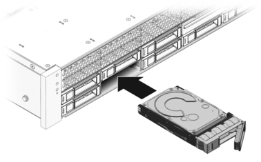
Installing a hard drive into the SPARC Enterprise T5140 and T5240 servers is a two-step process. You must first install a hard drive into the desired drive slot. Then you must configure that drive to the server.
Note - Sun SPARC Enterprise T5140 servers might have up to seven blank panels covering unoccupied drive slots. Sun SPARC Enterprise T5240 servers might have as many as fifteen blank panels covering unoccupied hard drive slots.
Hard drives are physically addressed according to the slot in which they are installed. If you install a hard drive as a replacement for a drive that was removed, the new drive must go into the same slot as the drive it is replacing.
Figure 64 Installing a Hard Drive (Illustrating Installation in a Sun SPARC Enterprise T5240 Server)
# cfgadm -al
This command should identify the Ap_id for the hard drive you plan to remove, as shown below.
Ap_id                          Type         Receptacle   Occupant     Condition
c0                             scsi-bus     connected    configured   unknown
c0::dsk/c1t0d0                 disk         connected    configured   unknown
c0::sd1                        disk         connected    unconfigured unknown
usb0/1                         unknown      empty        unconfigured ok
usb0/2                         unknown      empty        unconfigured ok
usb0/3                         unknown      empty        unconfigured ok
usb1/1                         unknown      empty        unconfigured ok
usb1/2                         unknown      empty        unconfigured ok
usb1/3                         unknown      empty        unconfigured ok
usb2/1                         unknown      empty        unconfigured ok
usb2/2                         unknown      empty        unconfigured ok
usb2/3                         unknown      empty        unconfigured ok
usb2/4                         unknown      empty        unconfigured ok
usb2/5                         unknown      empty        unconfigured ok
usb2/6                         unknown      empty        unconfigured ok
usb2/7                         unknown      empty        unconfigured ok
usb2/8                         unknown      empty        unconfigured ok
----------------------------
For example, the following shows drive c0:dsk/c1t1d1 being configured:
# cfgadm -c configure c0::sd1
where c0::sd1 is the disk that you want to configure.
# cfgadm -al
This command should identify the Ap_id for the hard drive that you installed. The output should indicate that the drive you installed is configured. For example, the output should look like this:
Ap_id                          Type         Receptacle   Occupant     Condition
c0                             scsi-bus     connected    configured   unknown
c0::dsk/c1t0d0                 disk         connected    configured   unknown
c0::dsk/c1t1d0                 disk         connected    configured   unknown
usb0/1                         unknown      empty        unconfigured ok
usb0/2                         unknown      empty        unconfigured ok
usb0/3                         unknown      empty        unconfigured ok
usb1/1                         unknown      empty        unconfigured ok
usb1/2                         unknown      empty        unconfigured ok
usb1/3                         unknown      empty        unconfigured ok
usb2/1                         unknown      empty        unconfigured ok
usb2/2                         unknown      empty        unconfigured ok
usb2/3                         unknown      empty        unconfigured ok
usb2/4                         unknown      empty        unconfigured ok
usb2/5                         unknown      empty        unconfigured ok
usb2/6                         unknown      empty        unconfigured ok
usb2/7                         unknown      empty        unconfigured ok
usb2/8                         unknown      empty        unconfigured ok
----------------------------


|