| C H A P T E R 2 |
|
Installing Modules and Options Into the Chassis |
This chapter describes how to perform new installations of modules and options in a Sun Blade 6048 chassis. The instructions and illustrations in this chapter refer to installing modules into one of the four shelves in the Sun Blade 6048 chassis. The instructions for each shelf are identical.

|
Caution - To keep the system from becoming top-heavy, make sure to populate the chassis from the bottom shelf up. |
Topics covered in this section include:
|
Each Sun Blade 6048 shelf supports up to 12 server modules.
To remove a filler panel from a slot and to install a server module into the corresponding vacant slot:
1. In the front of the system chassis, locate the slot into which you want to install the server module.
2. Remove the filler panel, if necessary.
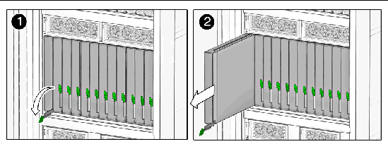
Rotate the lower ejector lever on the filler panel downward, and pull the filler panel out of the chassis.
FIGURE 2-1 shows the filler panel being removed from the chassis.
FIGURE 2-1 Removing a Filler Panel

| Note - Other filler panel should remain in any unused slots. |
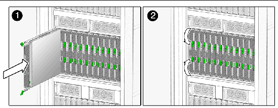
3. Position the server module vertically so that the ejectors are on the right.
See FIGURE 2-2.
FIGURE 2-2 Inserting the Server Module into the Chassis

4. Push the server module into the slot until the server module stops.
5. Rotate the ejectors down until they snap into place.
The server module is now flush with the chassis, and the ejectors are locked.
6. For each remaining server module to be installed, repeat Step 1 through Step 5.
7. Close the door of the system after all server modules are installed.
|
Each Sun Blade 6048 shelf can have zero, one, or two network express modules (NEMs) installed.
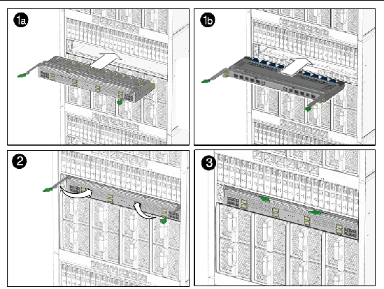
The NEM module will occupy either one or two NEM slots, depending on the type of NEM that you have. If the NEM occupies both NEM slots, so you can install only one module. If the NEM occupies one slot, you can install either one or two NEMs.
FIGURE 2-3 shows how to install both a dual-slot and single-slot NEM.

1. Align the NEM with the vacant NEM slot.
Ensure that the RJ-45 port connectors of the NEM are facing toward you and the ejectors are positioned at the top of the NEM.
2. Fully open the NEM ejector levers.
3. Slide the NEM into the vacant NEM chassis slot until you feel it stop.
In FIGURE 2-3 Panel 1a shows installation of a dual-slot NEM and Panel 1b shows installation of a single-slot NEM.
4. Secure the NEM by closing the ejector levers.
5. If you want to install another single-slot NEM, repeat Step 1 through Step 4.
|
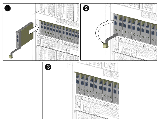
Each Sun Blade 6048 shelf supports up to 24 PCI ExpressModules (PCI EMs). The PCI EM slots are labeled PCI EM 0.0 to 11.1. FIGURE 2-4 shows how to install a
PCI EM.
FIGURE 2-4 Installing an PCI EM

1. Align the PCI EM with the vacant PCI EM slot.
Ensure that the indicator lights on the front panel of the PCI EM are facing toward you and that the PCI EM ejector lever on the bottom is fully opened.
2. Slide the PCI EM into the vacant PCI EM chassis slot.
The ejector lever starts to pop up as the module engages with the system slot.
3. Complete the installation by closing the ejector lever to secure the PCI EM in the chassis.
4. For each remaining PCI EM to be installed, repeat Step 1 through Step 3.
After installing modules and options into each shelf of the Sun Blade 6048 chassis, you are ready to connect the power cables and power on the system. See Chapter 3.
Copyright © 2007, Sun Microsystems, Inc. All Rights Reserved.