| C H A P T E R 3 |
|
Attaching Cables and Devices to Modules and Powering On the System Chassis |
This chapter describes how to connect the AC power cables, management network cables, and data network cables to the appropriate chassis modules. Finally, this chapter tells you how to power on the system chassis for the first time.
| Note - The instructions and illustrations in this chapter refer to cabling and powering on each of the four shelves in the Sun Blade 6048 chassis. The instructions for each shelf are identical. |
Topics covered in this chapter include:
This section covers the following topics:
|
Each chassis contains a chassis monitoring module (CMM) with two Ethernet (NET MGT) ports and one serial management (SER MGT) port available. This section provides instructions for attaching a local area network cable and a serial console cable to the management ports on the rear panel of a CMM.
1. Locate an Ethernet network management cable and a serial console cable.
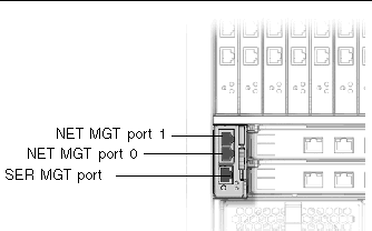
2. Attach the serial console cable to the SER MGT port on the rear panel of the CMM, and plug the other end of the cable to the serial terminal.
3. Plug the Ethernet cable into NET MGT 0 port on the CMM, and plug the other end of the Ethernet cable to your local area network.
| Note - The NET MGT 1 port is disabled by default. You can enable port 1 through the ILOM. See the Sun Blade 6048 Modular System Service Manual, 820-2863, for more information. |
|
This section provides instructions for attaching cables to the network express modules (NEMs).
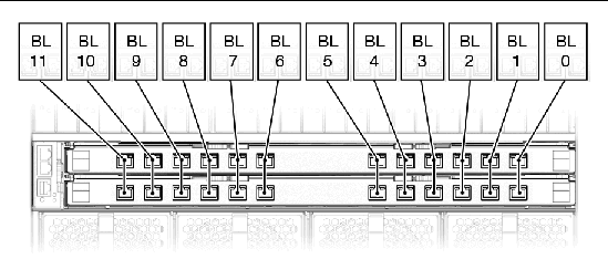
Each shelf in the Sun Blade 6048 chassis provides up to two NEM slots, labeled NEM 0-1 with 0 being the bottom NEM slot and 1 being the top NEM slot. Dual-slot NEMs occupy both slots for a single NEM, and single-slot NEMs occupy one of the slots.
FIGURE 3-2 shows the correspondence between NEM ports and blades on a Gigabit Ethernet NEM.
| Note - For details on the Infiniband NEM operation, refer to the Sun Blade 6048 Switched InfiniBand Network Express Module User’s Guide, 820-2189. |
FIGURE 3-2 NEM to Server Module Correspondence
1. Locate the cables needed for your configuration.
2. Connect the cable to the appropriate port on the NEM.
3. Attach the other end of the data cable to the appropriate data source.
|
This section provides instructions for attaching data network cables to the PCI ExpressModule (PCI EM).
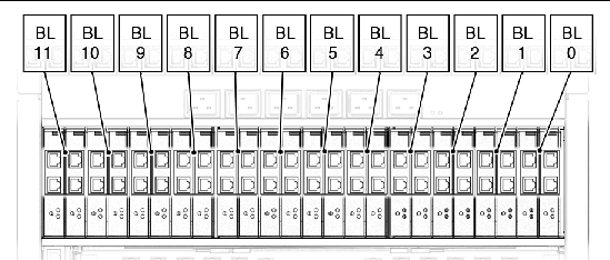
For each PCI EM installed, there are two external data ports provided. Each Sun Blade 6048 shelf provides 24 PCI EM slots, with 2 PCI EM slots assigned to each server module. The PCI EM slots are numbered PCI EM 0.0 to 11.1 right to left as viewed from the rear of the chassis.
FIGURE 3-3 shows how the NEMs correspond to the blades installed in the system.
FIGURE 3-3 Server Module to PCI EM Correspondence
| Note - The following procedure assumes that you have recorded the MAC address for each PCI EM data port. The PCI EM port MAC addresses are printed on the PCI EM board. |
1. Locate the cables needed for your configuration.
2. Plug the data network cable into the appropriate RJ-45 data port.
3. Attach the other end of the data network cable to the appropriate data source.
|
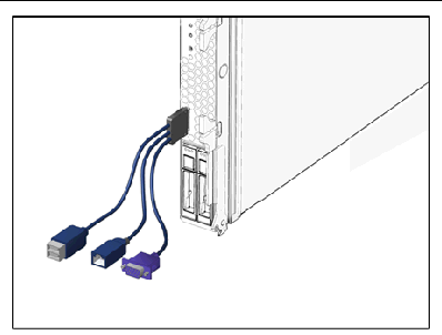
In a fully populated shelf, there are 12 server modules. A dongle cable is included with the Sun Blade 6048 chassis to provide USB, serial, and VGA I/O connections for the server modules. See FIGURE 3-4.
FIGURE 3-4 Dongle Cable for Server Module Connections
See the server module documentation for information about connectors for each server module.
|
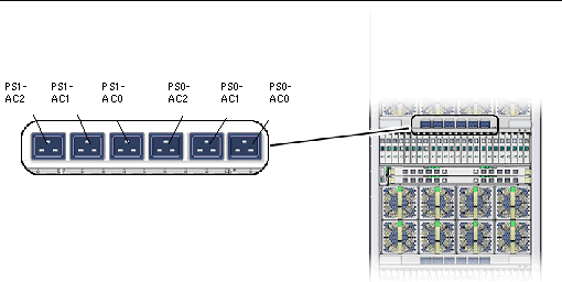
The Sun Blade 6048 AC power interface supplies main power to the modules in the system chassis. Each Sun Blade 6048 shelf includes two power supply modules that provide six power inlets. FIGURE 3-5 shows the AC power inlets.
1. Make sure that the front cabinet door is closed.
2. Locate six of the power cables shipped with the system.
3. Locate the AC inlets on the power interface on the rear of the chassis.
4. Open the metal retention clips for each power inlet.
5. In the rear of the chassis, plug six power cables into slot positions PS0-AC0, PS0-AC1, PS0-AC2, PS1-AC0, PS1-AC1, and PS1-AC2.
6. Secure the cables to the connector with the metal retention clip.
7. Plug the other end of the power cables into the power distribution unit (PDU).
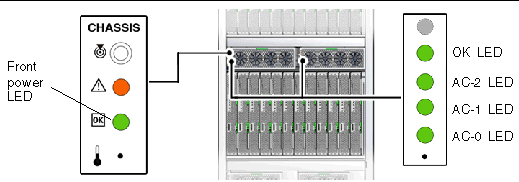
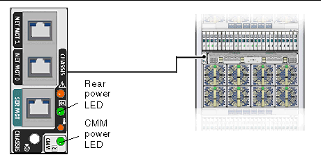
Main power is automatically distributed to the system chassis and the OK power LEDs on the CMM and front indicator module (FIM) flash.
Main power is automatically supplied to the system shelf as soon as the power supplies receive power. When the system shelf is powered up, main power is applied to all installed modules: CMM, NEMs, server modules, and PCI EMs.
| Note - This section describes the 8400 W power supply. Other power supply configurations might be available. For further information, refer to the product pages at http://sun.com/blades |
This section describes how to ensure that the system chassis is powered on and the server modules are powered on.
To ensure that the system shelf is powered up:
1. Make sure that all six of the AC power cables are attached from the power interface module to a power source.
For details, see To Attach the Power Cables to the AC Power Interface.
The system chassis automatically applies main power to all modules in the chassis after power is provided to the power supplies.
2. Make sure that main power is applied to the system shelf.
The OK power LED is a solid green light. There are OK power LEDs located on the front and rear of the chassis, as well as power supply LEDs shown in FIGURE 3-6.
| Note - See the server documentation for power-on information for the server modules. |
After attaching cables to I/O modules, attaching local devices to the server modules, and powering on the system, you are ready to configure the CMM and server module management network. See Chapter 4.
Copyright © 2007, Sun Microsystems, Inc. All Rights Reserved.