| Sun Storage J4200/J4400 Array Hardware Installation Guide |
| C H A P T E R 2 |
|
Installing Rails and Trays in Cabinets |
This document describes how to install the Sun Storage J4200 and J4400 Array Rail Kits in a cabinet, and how to install the J4200 and J4400 trays into a cabinet.
This document contains the following sections:
Before you begin to install the rail kit, do the following:
The rail kits for both the J4200 array and J4400 array contain the appropriate cabinet rails and all required mounting hardware for installing in any of the supported cabinet types. Each rail adjusts to cabinet rail depths from 24 inches (60.96 cm) to 36 inches (91.44cm).
FIGURE 2-1 Left and Right Mounting Rails (J4200 Array Rails Shown)
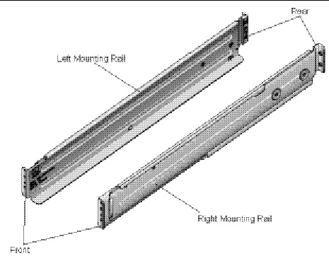
TABLE 2-1 lists the rail kit components for the J4200 array, and lists the rail kit components for the J4400 array:
|
Sun Rack 900/1000 cabinets and Universal 19” non-threaded cabinet |
||
|
Sun Rack 900/1000 cabinets and Universal 19” non-threaded cabinet |
||
You can install the rail kit in any of the following cabinets:
1. Select the cabinet in which you will be installing the array. Be sure the cabinet is installed as described in the cabinet installation instructions.
2. Stabilize the cabinet as described in the cabinet documentation.
3. If the cabinet has casters, make sure the casters are locked to prevent the cabinet from rolling.
4. Position the data host next to the cabinet in which the array will be installed.
Use the following procedure for the Sun Rack 900/1000 cabinet.
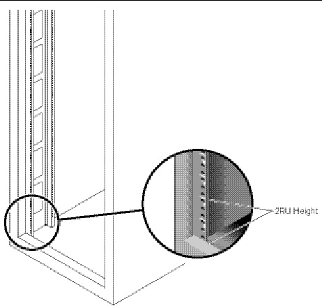
1. Starting at the bottom of the cabinet, locate the appropriate rack unit (RU) height. The J4200 array requires two standard mounting units (2RU) and the J4400 array requires four standard mounting units (4RU) of vertical space in the cabinet.
| Note - Each standard rack unit (RU) consists of three mounting holes in the left and right cabinet rails. |
FIGURE 2-2 Cabinet Rail 2RU Mounting Holes for the J4200 Array

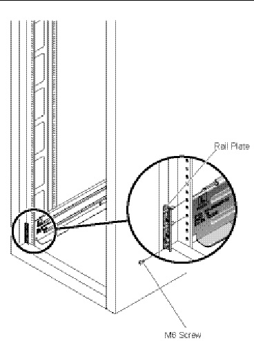
2. Start at the front of the cabinet. Install one of the M6 rail plate brackets to each side of the rack (see FIGURE 2-3).
a. With the text on the bracket facing toward you, align the two pins of the rail plate bracket with the holes on the cabinet rail.
b. For the J4200 and J4400 rack mounting plates, insert an M6 screw in the lower hole and tighten. For the J4400, insert an additional M6 screw in the top hole.
3. At the back of the cabinet, repeat step 2 to install the remaining two M6 rail plate brackets.
FIGURE 2-3 Attaching the Rail Plates to the Cabinet Rail for the J4200 Array
4. For ease of installation, attach the left and right rails from the back of the cabinet. Follow these steps for the left rail:
a. Position the front of the rail inside the cabinet, and insert the rail holes onto the two pins of the front rail plate bracket.
| Note - Rails are labeled L (left), Front and Rear, and R (right), Front and Rear. (See FIGURE 2-1.) |
b. Adjust the rail length to fit the size of the cabinet.
Be sure to align the rail flange so that the mounting holes at the back correspond to those at the front of the cabinet.
c. Insert the two holes of the rail flange onto the two pins on the back rail plate bracket.
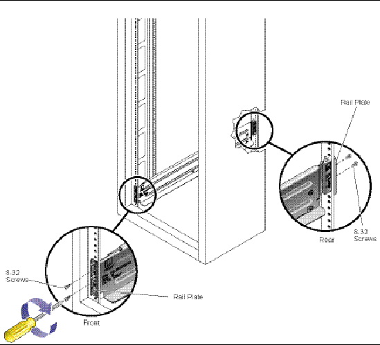
d. Insert an 8-32 screw into the first and second hole positions (into the first through fourth hole positions for the J4400 array). Use the #2 Phillips screwdriver to tighten each screw to secure the rail to the rack.
e. Repeat Step a through Step d for the right rail.
5. Install two 8-32 screws in the front of the J4200 rail, and four 8-32 screws in the front of the J4400 rail.

|
Caution - Make sure you install the front screws into the rail bracket to secure the rail to the rack and to avoid damage to the device or person installing the device. |
FIGURE 2-4 Attaching and Securing the Left Rail to the Cabinet Rail for the J4200 Array
Installation of the rail kit is complete. You are now ready to install the array chassis onto the cabinet rails. See the Preparing to Install a Tray in a Cabinet for installation instructions.
Use the following procedure for Sun StorEdge Expansion or Sun Fire cabinet.
|
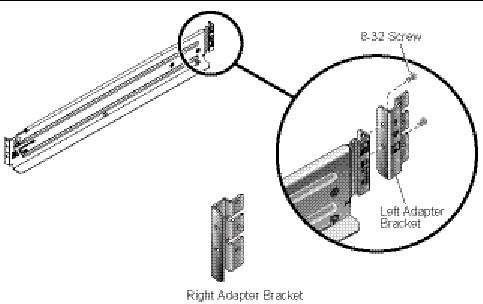
Attaches to the rear of the left and right rail assembly. These brackets allow access to the power cabling area at the back of the cabinet. |
||
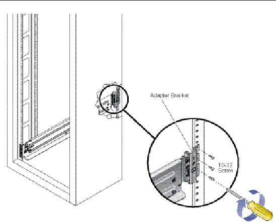
1. Install the rear rail adapter brackets onto the left and right rails. (See FIGURE 2-5.)
| Note - Rails are labeled L (left), Front and Rear, and R (right), Front and Rear. (See FIGURE 2-1.) |
2. Insert and tighten two 8-32 screws (four 8-32 screws for the J4400) to secure the adapter bracket to each rail.
FIGURE 2-5 Attaching the Adapter Brackets to the Rail (J4200)
3. Starting at the bottom of the cabinet, locate the appropriate mounting unit height. The J4200 array requires two standard rack units (2RU) and the J4400 array requires four standard rack units (4RU) of vertical space in the cabinet (See FIGURE 2-6).
| Note - Each standard rack unit (RU) consists of three mounting holes in the left and right cabinet rails. |
FIGURE 2-6 Locating the Rack Unit (RU) Height for the J4200 Array
4. At the front of the cabinet, install the 10-32 rail plate brackets to the left and right cabinet rails.
a. With the text on the bracket facing our, align and insert the two pins of the rail plate bracket into the cabinet rail holes.
b. For the J4200 and J4400 rack mounting plates, insert a 10-32 screw in the lower hole and tighten. For the J4400, insert an additional 10-32 screw in the top hole.
FIGURE 2-7 Attaching the Rail Plates to the Cabinet Rail (J4200)

5. For ease of installation, attach the left and right rails from the back of the cabinet. (See FIGURE 2-8.) Follow these steps for the left rail:
a. Position the front of the rail inside the cabinet, insert the rail holes onto the two pins of the front rail plate bracket.
b. Adjust the rail length to fit the size of the cabinet.
Be sure to align the rail flange so that the mounting holes at the front correspond to those at the back of the cabinet.
c. Align and insert the rear rail pin into the cabinet rail hole.
d. Add three 10-32 screws (six 10-32 screws for the J4400) to secure the rear adapter to the rack. (See FIGURE 2-8.)
e. From the front of the cabinet, insert two 8-32 screws (four 8-32 screws for the J4400) to secure the rail to the cabinet.
f. Repeat Step a through Step e for the right rail.
|
|
Caution - Make sure you install the front screws into the rail bracket to secure the rail to the rack and to avoid damage to the device or person installing the device. |
FIGURE 2-8 Securing the Adapter Brackets to the Cabinet Rail (J4200)
Installation of the rail kit is complete. You are now ready to install the array chassis onto the cabinet rails. See the Preparing to Install a Tray in a Cabinet for installation instructions.
Use the following procedure to attach the rail kit to any 19-inch wide, 4-post EIA-compatible rack, or cabinet with unthreaded cabinet rails.
|
Snaps over the rail mounting holes in the left and right back cabinet rails |
||
|
Snaps over the rail mounting holes in the left and right back cabinet rails |
||
1. Starting at the bottom of the cabinet, locate the appropriate mounting unit height. The J4200 array chassis requires two standard mounting rack units (2RU) of vertical space in the cabinet. The J4400 array chassis requires four standard mounting rack units (4RU) of vertical space in the cabinet.
| Note - Each standard rack unit (RU) consists of three mounting holes in the left and right cabinet rails. |
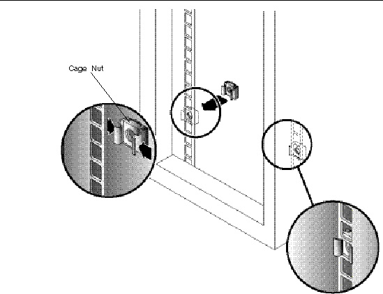
2. At the front of the cabinet, snap a cage nut into the lower hole of the 2RU of the right rail (and an additional cage nut in the top hole of the 4RU for the J4400). Repeat for the left rail. (See FIGURE 2-9.)
FIGURE 2-9 Inserting Cage Nuts Into the Cabinet Rail Mounting Holes (J4200)
3. Install the left and right square hole rail plate brackets (four brackets total for J4400).
a. For the J4200 and J4400 rack mounting plates, insert an M6 screw in the lower hole and tighten. For the J4400, insert an additional M6 screw in the top hole.
b. Using the #2 Phillips screwdriver, tighten the screws to secure the plates to the rail.
4. At the back of the cabinet, snap a cage nut into the lower hole of the 2RU of the right rail (and an additional cage nut in the top hole of the 4RU for the J4400). Repeat for the left rail. (See FIGURE 2-9.)
5. For the J4200 and J4400 rack mounting plates, insert an M6 screw in the lower hole and tighten. For the J4400, insert an additional M6 screw in the top hole.
Be sure to align the rail flange so that the mounting holes at the front correspond to those at the back of the cabinet.
a. Insert an M6 screw into the lower hole of the rail plate bracket (lower two holes for J4400).
b. Using the #2 Phillips screwdriver, tighten the screws to secure the plates to the rail.
6. For ease of installation, attach the left and right rails from the back of the cabinet. Follow these steps for the left rail:
a. Position the front of the rail inside the cabinet, and insert the rail holes onto the two pins of the front rail plate bracket.
b. Adjust the rail length to fit the size of the cabinet.
Be sure to align the rail flange so that the mounting holes at the front correspond to those at the back of the cabinet and the rail is level.
c. Align the two holes of the rail flange with the two pins on the back rail plate bracket.
d. Install two 8-32 screws to secure the rail to the rack (install four screws for the J4400), as shown in FIGURE 2-8.
e. Repeat Step a through Step d for the right rail.
7. At the front of the cabinet, insert two 8-32 screws (four screws for J4400) in the remaining holes of the left and right brackets and tighten to secure the rail to the cabinet.
|
|
Caution - Make sure you install the front screws into the rail bracket to secure the rail to the rack and to avoid damage to the device or person installing the device. |
FIGURE 2-10 Attaching the Rails to the Cabinet

Installation of the rail kit is complete. You are now ready to install the array chassis onto the cabinet rails. See the Preparing to Install a Tray in a Cabinet for installation instructions.
The J4400 weighs up to 91 pounds (42 kg) fully loaded. You should remove the disks before sliding the tray into the cabinet so that it is easier to lift. Removing a Disk Drive describes this procedure.
|
|
Caution - The power supplies in this equipment can produce high energy hazards. Only trained personnel with authorized access to this equipment should remove and replace modules in the system. |
|
|
Caution - The replacement disk drive must be the same capacity and same type as the disk drive it is replacing. |
|
|
Caution - Never remove a disk drive unless the ID/Status LED is blue (see FIGURE 1-1). If you need to remove multiple disk drives, always remove and replace one disk drive at a time. |
| Note - The disks are hot-swappable and you do not need to disconnect power from the system or other components in order to replace one of these parts. |
This section describes how to remove a disk drive.
1. From the front of the disk tray, locate the disk drives (see FIGURE 2-11) you want to remove. The Activity LED is off and the ID/Status LED is blue, indicating that data is not being transferred to or from the disk and that the disk drive is ready to remove.
|
|
Caution - Potential loss of data access - Data might be lost if an active disk drive is removed. If you remove an active disk drive accidentally, wait at least 30 seconds before reinserting it. |
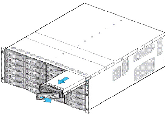
2. Press the release button in and to the right to release the disk ejection lever.
3. Pull the disk ejection lever fully open to unlock and partially eject the disk drive from the tray.
4. Grasp the middle of the disk drive body and pull it toward you to remove it from the tray.
FIGURE 2-11 Removing a Disk Drive From a J4400 Array Disk Tray
|
|
Caution - For products with multiple power cords, all power cords must be disconnected to completely remove power from the system. |
This section describes installing a tray in a cabinet.
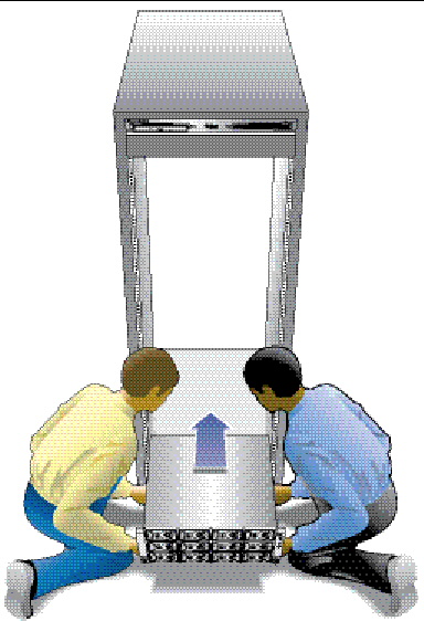
1. Using two people, one at each side of the tray, carefully lift and rest the tray on the bottom ledge of the left and right rails (FIGURE 2-12).
|
|
Caution - Use care to avoid injury. A J4200 tray can weigh up to 53 pounds (24 kg) and a J4400 tray can weigh up to 91 pounds (42 kg). |
FIGURE 2-12 Positioning the J4200 Array in the Cabinet
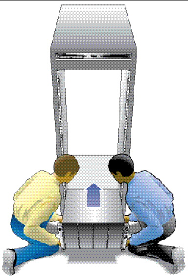
|
|
Caution - Given the excessive weight of a fully loaded J4400 chassis (91 lbs/42 kg), you should remove the components before lifting the tray, as shown in FIGURE 2-13 and as described in Removing a Disk Drive. |
FIGURE 2-13 Positioning the J4400 Array in the Cabinet
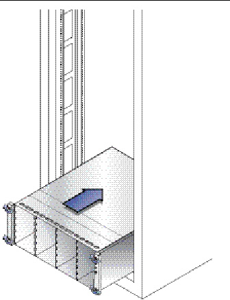
2. Carefully slide the tray into the cabinet until the front flanges of the tray touch the vertical face of the cabinet (FIGURE 2-14 and FIGURE 2-15).
FIGURE 2-14 Sliding the J4200 Array Into the Cabinet Rail
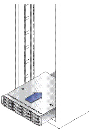
FIGURE 2-15 Sliding the J4400 Array Into the Cabinet Rail
3. You should now replace the disks into the J4400, as described in Replacing a Disk Drive.
This section describes how to replace a disk drive.
|
|
Caution - Follow normal ESD precautions and use care when handling a disk drive. |
1. Ensure the disk drive is the same type and same capacity as the disk that was removed.
2. Ensure the disk ejection lever is in the fully extended position (see FIGURE 2-16).
3. Align the disk drive with the open slot and slide the drive into the disk tray.
4. Push the disk drive into the tray slot until the disk ejection lever engages the tray connectors and begins to swing closed.
5. Press the disk ejection lever closed until it locks in place to seat the drive and lock it into the tray.
FIGURE 2-16 Inserting a Disk Drive in a J4400 Array Disk Tray

6. After the disk drive is locked in place, the Activity LED will be steady green to indicate a ready state.
1. Install and tighten the captive screw or screws on each side of the front of the tray to secure the tray to the cabinet (FIGURE 2-17 and FIGURE 2-18).
2. Replace the components back into the appropriate places (J4400 only).
FIGURE 2-17 Securing the J4200 Array to the Front of the Cabinet Rail

FIGURE 2-18 Securing the J4400 Array to the Front of the Cabinet Rail
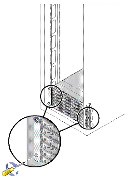
3. Stabilize the back of the J4200/J4400 in the cabinet. At the back, slide a system locking clip onto each lower corner of the J4200/J4400 chassis (FIGURE 2-19 and FIGURE 2-20). You can use a Phillips Head screwdriver for leverage to help you push in the clip.
FIGURE 2-19 Inserting the J4200 Array System Locking Clip
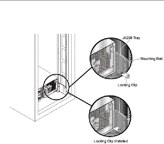
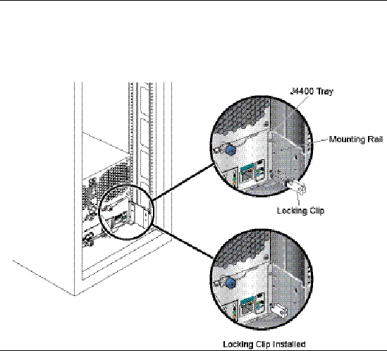
FIGURE 2-20 Inserting the J4400 Array System Locking Clip
After you have installed J4200/J4400 trays into a cabinet, you are now ready to connect the devices and power on the trays. Refer to Chapter 3 Connecting Devices and Powering On for additional information.
| Sun Storage J4200/J4400 Array Hardware Installation Guide | 820-3218-14 |
© © 2009 Sun Microsystems, Inc. All rights reserved.