| C H A P T E R 1 |
|
Overview |
This document provides detailed procedures for installing the hardware and software for the Dual Port 4x DDR IB PCIe Host Channel Adapter card. The cards described in this guide have the following main features:
| Note - The PCI Express (or PCIe) interface is sometimes called PCI-E. |
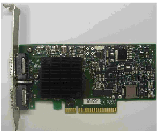
FIGURE 1-1 Dual Port 4x DDR IB PCIe Host Channel Adapter With Tall Bracket

Each IB-HCA card includes the following interfaces:
The Dual Port 4x DDR IB PCIe Host Channel Adapter device is compliant with the InfiniBand Architecture Specification, Release 1.2. It has two compliant 4X InfiniBand ports, A and B. The IB-HCA card provides access to these ports by means of two 4X InfiniBand connectors for external InfiniBand copper cables also compliant with the InfiniBand Architecture Specification, Release 1.2. Connector 1 connects to port A of the device, while connector 2 connects to port B.
Furthermore, the IB-HCA card is embedded with a ‘media detect circuit’ that supports external InfiniBand fiber solutions. These are connected to the InfiniBand port connectors using active media converters, such as Emcore’s QTR3400 Smart Module or Fujitsu’s FPD-010R008-0E o-microGiGaCN.
The Dual Port 4x DDR IB PCIe Host Channel Adapter device has eight Tx/Rx pairs of SerDes providing for a PCI Express x8 interface, version 1.0a compatible. The device can be either a master initiating the PCI Express bus operations or a slave responding to PCI bus operations. The PCI Express bus can connect to either a host CPU in an IB-HCA application or to an I/O device (such as Gigabit Ethernet) when used as a Target Channel Adapter.
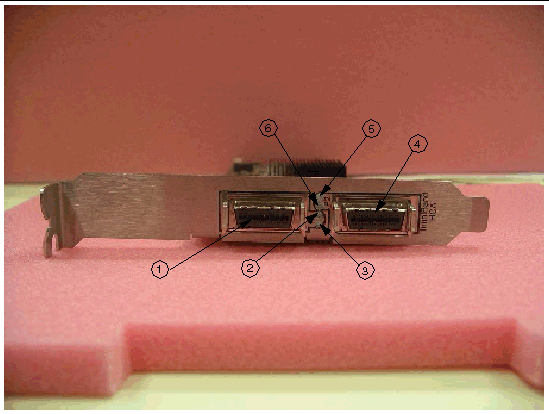
The board has four LEDs located on the I/O panel - 2 LEDs per 4X port. See TABLE 1-1.
The physical link (green) illuminates once VAPI (InfiniBand Verbs API) is started and a physical connection is made between two nodes. The data activity link (amber) illuminates once the InfiniBand network is discovered over the physical link. The activity link is a steady yellow when it is discovered but no data is being passed. The activity link blinks when data is being passed. If the LEDs are not active, either the physical or the logical (or both) connections have not been established. See FIGURE 1-2.
Short brackets have the same port and LED footprints as tall brackets. See Appendix B.
FIGURE 1-2 I/O Panel With Dual Ports and LEDs (Tall Bracket)

A three-pin header, designated with reference name J5 on the IB-HCA card, is provided as the I2C compatible interface.
All adapter cards receive power from the PCI Express Edge connector. All other required power voltages are generated by on-board switch mode regulators. For power consumption see Appendix A.
The IB-HCA card support multiple memory devices through the PCI Express, Flash, and I2C-compatible interfaces.
The IB-HCA card utilizes the PCI Express interface to store and access IB fabric connection information on the system memory.
Copyright © 2008, Sun Microsystems, Inc. All Rights Reserved.