| C H A P T E R 2 |
|
Mounting the Sun Blade 6000 Chassis in a Rack |
This chapter describes how to install the Sun Blade 6000 modular system in a rack.
This section covers topics listed in the following table.
|
Remove preinstalled chassis components if you are installing the chassis manually. |
|
|
Install components that you removed and additional system options. |
Before mounting the chassis in a rack, keep in mind the following:
You will need the following tools and supplies to install the base modules and options into chassis and mount the chassis into a rack:
Internal modules and options are electronic components that are extremely sensitive to static electricity. Ordinary amounts of static from your clothes or work environment can destroy components.
To prevent static damage whenever you are accessing any of the internal components, you must:
If you are mounting the chassis in a rack without a mechanical lift, refer to the following procedures to remove the preinstalled components in the chassis:
|
FIGURE 2-1 shows how to remove the power supplies.
FIGURE 2-1 Removing a Power Supply
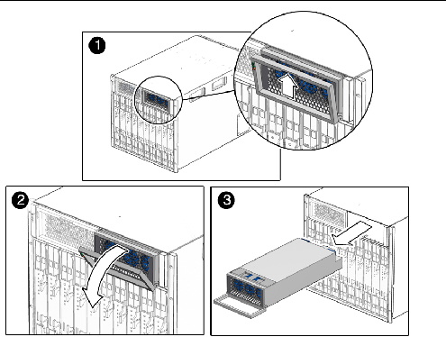
1. In the front of the chassis, locate the power supply to be removed.
2. Press and hold the green button on top of the power supply handle frame.
3. Rotate the power supply handle away from the power supply and down.
4. Pull the power supply out slightly, until you can support the bottom with one hand. Do not pull the power supply out of the chassis with the handle.
5. Pull the power supply all the way out of the chassis, supporting it with two hands as soon as possible.
6. Repeat Step 1 through Step 5 for the second power supply.
| Note - Store the power supply modules in a safe place. After the chassis is rackmounted, reinstall the power supply as described in How to Install Power Supply Modules. |
|
FIGURE 2-2 shows how to remove a system fan module.
FIGURE 2-2 Removing a Fan Module
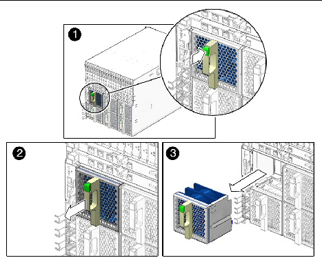
1. In the rear of the chassis, locate the fan module that you want to remove.
2. Press and hold the green button on the fan handle.
3. Pull out the rear fan module in a smooth motion until it is free from the chassis.
4. Repeat Step 1 through Step 3 until you have removed all six rear fan modules from the chassis.
| Note - Store the rear fan modules in a safe place. After the chassis is rackmounted, you will need to reinstall the rear fan modules into the chassis. This procedure is described in How to Install Rear Fan Modules. |
|
FIGURE 2-3 shows how to remove the NEMs.
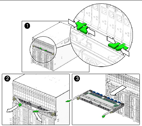
1. In the rear of the chassis, locate the NEM that you want to remove.
2. Press together and hold the ejector buttons on both right and left ejector levers.
3. To unlatch the NEM from the chassis, open the ejector levers by rotating them outward.
4. Holding the opened ejector levers, pull the NEM toward you until you are able to pull the rest of the module out by hand.
5. Repeat Step 1 through Step 4 if you have another NEM to remove.
| Note - Store the NEMs in a safe place. After the chassis is rackmounted, you will need to reinstall the NEMs into the chassis. This procedure is described in How to Install NEMs. |
|
FIGURE 2-4 shows how to remove the PCIe EMs.
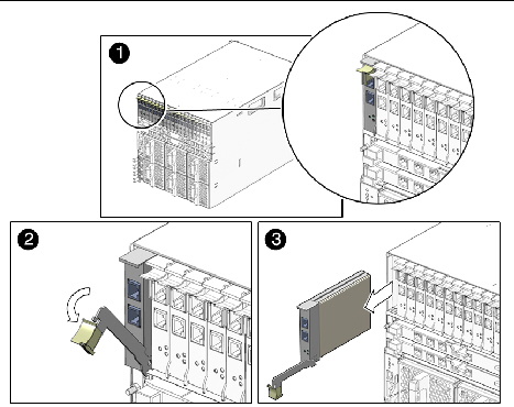
1. In the rear of the chassis, locate the PCIe EM that you want to remove.
2. Place one finger on top of ejector-lever handle, and rotate the handle downward.
3. Pull the ejector lever toward you, and pull the PCIe EM forward until you are able to pull the rest of the module out by hand.
4. Repeat Step 1 through Step 3 until you have removed all installed PCIe EMs from the chassis.
| Note - Store the PCIe EMs in a safe place. After the chassis is rackmounted, you will need to reinstall the PCIe EMs into the chassis. This procedure is described in How to Install PCIe EMs. |
|
FIGURE 2-5 shows how to remove the CMM.
| Note - The following illustration shows the A90-D chassis CMM. The removal process for the previous version of the CMM is the same. |
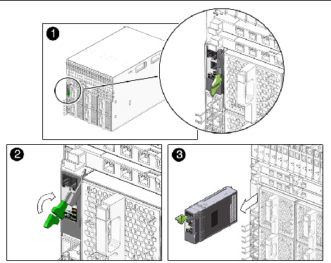
1. In the rear of the chassis, locate the CMM.
2. Press together and hold the ejector buttons on the module ejector lever.
3. To unlatch the module from the chassis, pull the ejector lever away from the module and up.
4. Pull the ejector lever toward you until you are able to pull the rest of the module out by hand.
| Note - Store the CMM in a safe place. After the chassis is rackmounted, you will need to reinstall the CMM into the chassis. This procedure is described in How to Install the CMM. |
After unpacking the system chassis and verifying that all the components in your order were received, proceed to the instructions on the Sun Blade 6000 Chassis Rack Alignment Template, 263-2755, for detailed instructions on mounting the chassis.
This document is included with the Sun Blade 6000 modular system rackmount kit and is also available on the Sun Blade 6000 modular system documentation site at:
http://docs.sun.com/app/docs/prod/blade.6000mod~blade6000#hic
After mounting the chassis in the rack, if you have removed modules to install the chassis manually, replace the modules as shown in: Installing Modules and Options.
This section describes how to perform new installations of modules and options into a Sun Blade 6000 chassis. Topics covered in this section include:
|
The Sun Blade 6000 chassis supports up to 10 server or storage modules.
Use the following procedures to remove a filler panel from a slot and to install a server module into the corresponding vacant slot.
1. In the front of the system chassis, locate the desired slot in the chassis.
2. Remove the filler panel, if necessary.
FIGURE 2-6 shows the filler panel being removed from the chassis.
FIGURE 2-6 Removing a Filler Panel
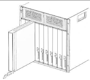
3. Rotate the lower ejector lever on the filler panel downward, and pull the filler panel out of the chassis.
| Note - Other filler blades should remain in any unused slots as they ensure the chassis complies with FCC limits on electromagnetic interference (EMI). |
4. Position the server or storage module vertically so that the ejectors are on the right.
See FIGURE 2-7.
FIGURE 2-7 Inserting the Server Module into the Chassis
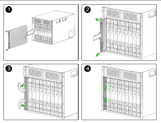
5. Push the server or storage module into the slot until the module stops.
6. Rotate the ejectors down until they snap into place.
The server or storage module is now flush with the chassis and the ejectors are locked.
7. For each remaining server or storage module to be installed, repeat Step 1 through Step 6.
|
FIGURE 2-8 shows how to install the power supplies.
FIGURE 2-8 Installing a Power Supply
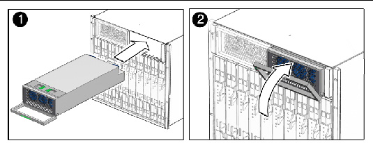
1. In the front of the system chassis, locate a vacant power supply slot.
Ensure that the power supply unit is facing up and the three LED holes appear on the left when installing the power supply module.
2. Pull the power supply handle out and away from the power supply.
3. Align the power supply unit with the power supply slot.
4. In a smooth motion, slide the power supply into the power supply slot until the unit engages with the internal connectors.
5. Push the power supply handle back toward the power supply until it clicks into place.
6. Repeat Step 1 through Step 5 until you have reinstalled both power supply modules in the chassis.
|
The Sun Blade 6000 chassis can have 0, 1, or 2 network express modules (NEMs) installed. FIGURE 2-9 shows how to install a NEM.
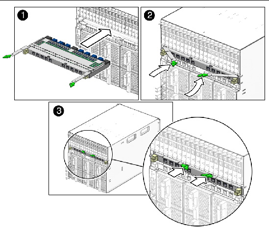
1. Align the NEM with the vacant NEM slot.
Ensure that the RJ-45 port connectors of the NEM are facing toward you and are positioned at the top of the NEM.
2. Fully open the NEM ejector levers.
3. Slide the NEM into the vacant NEM chassis slot until you feel it stop.
4. Secure the NEM by closing the ejector levers.
5. For each remaining NEM to be installed, repeat Step 1 through Step 4.
|
The Sun Blade 6000 chassis supports up to 20 PCIe ExpressModules (PCIe EMs). It arrives with 20 filler panels installed in each PCIe EM slot labeled PCIe EM 0.0-9.1. FIGURE 2-10 shows how to install a PCIe EM.
FIGURE 2-10 Installing an PCIe EM
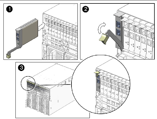
1. Align the PCIe EM with the vacant PCIe EM slot.
Ensure that the indicator lights on the front panel of the PCIe EM are facing toward you and that the PCIe EM ejector lever on the bottom is fully opened.
2. Slide the PCIe EM into the vacant PCIe EM chassis slot.
The ejector lever starts to pop up as the module engages with the system slot.
3. Complete the installation by closing the ejector lever to secure the PCIe EM in the chassis.
4. For each remaining PCIe EM to be installed, repeat Step 1 through Step 3.
|
FIGURE 2-11 shows how to install a fan module.
FIGURE 2-11 Installing a Fan Module
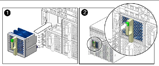
1. In the back of the system chassis, locate a vacant fan module slot.
2. Using both hands, align the fan module with the vacant slot.
Make sure that the green button on the handle of the fan module is at the top of the fan.
3. Slide the fan module into the vacant slot until the front panel meets the fan controller assembly connectors.
You should hear or feel a click when the fan engages with the fan.
4. Repeat Step 1 through Step 3 until you have reinstalled all six rear fan modules in the chassis.
|
FIGURE 2-12 shows how to install a CMM.
| Note - The following illustration shows the A90-D chassis CMM. The removal procedure for the previous version of the CMM is the same. |
FIGURE 2-12 Installing the CMM
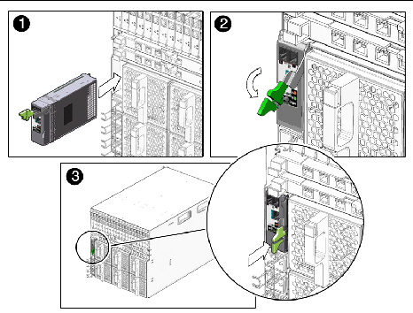
1. Align the CMM with the CMM slot.
Ensure that the CMM indicator lights of the CMM on the front panel are on the top of the module.
2. Slide the CMM into the vacant CMM chassis slot.
Ensure that the CMM engages with the system chassis guidance system.
3. Complete the installation by closing the ejector lever to secure the CMM in the chassis.
4. For each remaining CMM to be installed, repeat Step 1 through Step 3.
Copyright © 2010, Oracle and/or its affiliates. All rights reserved.