
This chapter contains an illustrated parts breakdown to the field replaceable
unit (FRU) level. The illustrated parts breakdown in the following pages is
intended to help you identify and replace the components in the GT Graphics Subsystem
.
Note -
Many of the items listed in the parts lists are not field-replaceable units
(identified by an asterisk [*] next to the part number). These items are
included for reference only.
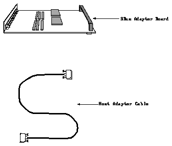
Figure 6-1
SBus Adapter Board and Host Adapter Cable Illustrated Parts Breakdown
Table 6-1
GT SBus Adapter Board and Host Adapter Cable Parts List
Key Description Part Number
1 SBus Adapter Board 501-1693-01
2 Host adapter cable 530-1684-02

Figure 6-2
Color Monitor and Cables Illustrated Parts Breakdown
Table 6-2
Color Monitor Parts List
Key Description Part Number
1 21" Color Video Monitor and power cable 365-1068-01
2 Video cable 530-1509-02
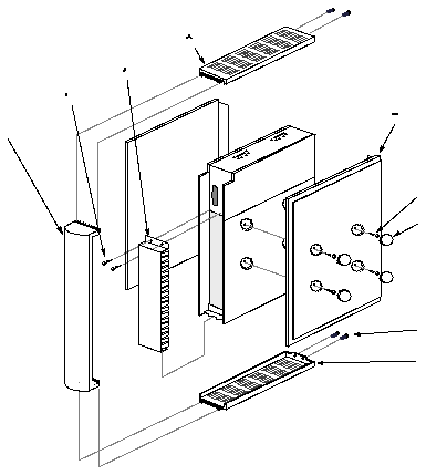
Figure 6-3
Graphics Tower Trim Illustrated Parts Breakdown
Table 6-3
Graphics Tower Trim Parts List
Key Description Part Number
1 Bezel, front 330-1335*
2 Screw, M4 \xb4 0.7 240-1372*
3 Backplane EMI Cover 340-1461*
4 Top cover 330-1090*
5 Side panel 330-1071*
6 Screw, M4 \xb4 1-1/16 240-1368*
7 Cosmetic screw cover cap 330-1089*
8 Bottom cover 330-1067*
9 Legs (not shown) 540-1531*
10 Cable management brackets (not shown) 330-1116*
* This part number is not a field-replaceable unit.

Figure 6-4
Graphics Tower Printed Circuit Boards Illustrated Parts Breakdown
Table 6-4
Graphics Tower Printed Circuit Boards Parts List
Key Description Part Number
1 Foreplane EMI cover 340-2524-01*
2 Foreplane connector 501-1694-01
3 M2.5 \xb4 16mm hex-head screw (6) 240-1287*
4 Frame Buffer Board 501-1624-02
5 Graphics Processor Rendering Pipeline Board 501-1726-01
6 Graphics Processor Front End Board 501-1692-01
7 Snap-in Nylon standoff 230-1156*
* This part number is not a field-replaceable unit.
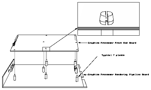
Figure 6-5
Graphics Processor Rendering Pipeline and Front End Board Assemblies
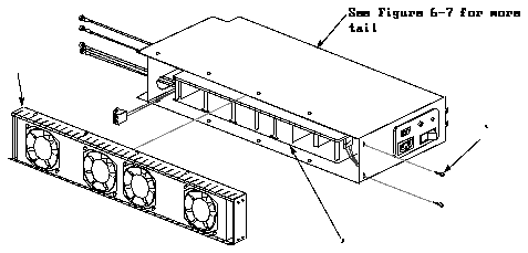
Figure 6-6
Power Supply/Fan Module Illustrated Parts Breakdown
Table 6-5
Power Supply/Fan Module Parts List
Key Description Part Number
1 Fan tray assembly 540-2051-01
2 M4 \xb4 0.7 hex-head screw 240-1372*
3 Power supply, three-slot 300-1022-01
* This part number is not a field-replaceable unit.

Figure 6-7
Power Supply Subassembly Illustrated Parts Breakdown
Table 6-6
Power Supply Subassembly Parts List
Key Description Part Number
1 Power supply, three-slot 300-1022-01
2 Grommet, flex nylon 230-1089*
3 Cover, power supply 340-1451*
4 Screw, M4 \xb4 0.7 hex-head 240-1372*
5 Power convenience module 370-1178*
6 Kep nut, M4 240-1373*
7 Fuse, 15 amp, 250V slow-blow - for 115V (not shown) 140-1019-01
Fuse, 6.3 amp, 250V time delay - for 230V (not shown) 140-1030-01
* This part number is not a field-replaceable unit.
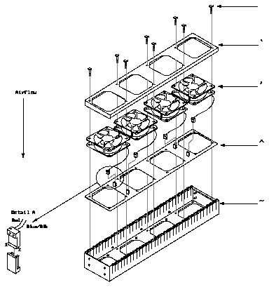
Figure 6-8
Fan Tray Assembly Illustrated Parts Breakdown
Table 6-7
Fan Tray Assembly Parts List
Key Description Part Number
1 Screw, M4 \xb4 0.7 240-1374*
2 Bracket, fan 340-1505*
3 Fan assembly, axial 540-2055*
4 PCB, fan 501-1773*
5 Tray, fan 340-1452*
* This part number is not a field-replaceable unit.

Figure 6-9
Cardcage Assembly Illustrated Parts Breakdown
Table 6-8
Cardcage Assembly Parts List
Key Description Part Number
1 M4 \xb4 0.7 hex-head screw 240-1372*
2 Backplane EMI cover bracket 330-1144*
3 Backplane assembly, three-slot 501-1127-06
4 Cardcage, three-slot 340-1448*
* This part number is not a field-replaceable unit.
