
This chapter explains how to install and remove the 1.05 Gbyte hard disk drive in the SBus Expansion Subsystem.
Caution -

Before you begin:
Recently released Sun systems and peripherals are now supplied with new regulated (active) SCSI terminators. Previously, Sun supplied standard SCSI terminators. Both types are shown below.

All SCSI systems must be terminated at the first and last units attached to the SCSI bus. A terminator is built in to all SBus SCSI cards and to all host systems. For the last unit attached to the SCSI bus, the new regulated terminators provide the improved impedance matching required for fast SCSI.
A bus is a signal route to which several parts of a computer system can be connected so that signals can pass between them. The total length of a SCSI bus includes:
When installing disk drives in the SBus Expansion Subsystem, you must attach an external SCSI cable from the SBus Expansion Subsystem to the computer system.
The maximum SCSI bus length is 6 meters (20 feet). If you have other SCSI devices connected to your computer system (such as external SCSI disk drives, tape drives or CD-ROM drive), refer to the manual that was shipped with your SCSI device to determine the SCSI bus length. You cannot exceed 6 meters for each SCSI bus. Refer to Appendix A for more information.
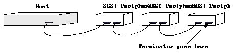
The regulated terminators must be used for all 50-pin SCSI busses having fast SCSI drives on a fast SCSI host.
Devices with the 3-row 50-pin D connector or the 50-pin ribbon connector (old- style connectors) should not be used on the same bus with fast SCSI devices.
The mixing of fast SCSI devices and old-style connector devices in the same daisy chain is not recommended. If fast SCSI devices and old-style connector devices must be used in the same system, the old-style connector devices should be connected to a separate SCSI port that doesn`t contain fast SCSI devices.
If you have the SunOS 2.x operating system, target addresses 0 through 3 are supported for hard disk drives. If you have the SunOS 5.x operating system, target addresses 0 through 6 are supported for hard disk drives. This determination of your operating system is described in Chapter 1.
Refer to the handbook that is appropriate for your operating system to determine which SCSI addresses are available to you.
Before you set the disk drive target address jumpers on the drive, determine the target addresses used by the system.
Note - Your system may have multiple SCSI host (port) controllers installed. Each SCSI device on an individual SCSI host controller must be assigned a separate and unique target address.
If all target addresses (0 through 3) in the internal SCSI bus of the computer system (SCSI bus 0) are assigned, you must add an SBus card to the system to add another SCSI port (bus). The first additional SCSI bus is named SCSI bus 1. The second SCSI bus is named SCSI bus 2. You can add as many SCSI buses to your system as supported by your operating system.
To determine the target addresses of your system:
You should now see the OK prompt.
If your system is not the host SCSI device, type probe-scsi-all.
If you need help with the commands listed here, or help in understanding the results of these commands, see the handbook that came with the disk drive.
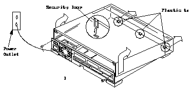
To remove the cover of the system unit:
If you are installing the drive into a new subsystem, plug the power cord into the back of the subsystem and into a grounded AC outlet. Do not turn the subsystem on.
The wrist strap provides grounding between your body and the chassis for static electricity. Electric current and voltage do not pass through the wrist strap.
Caution -

To attach the wrist strap:
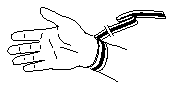
Figure 4-2 Wrist Strap
Note - Do not have the wrist strap attached and the system powered up when you handle the drive to verify the jumper settings.
Two types of drive kits can be ordered:
If you ordered a complete drive kit, the box should contain:
If you ordered a replacement drive, the kit will contain only the disk drive.
To unpack the drive:
Compare the packing list with the equipment you received.
The three sets of jumper blocks on the 1.05 Gbyte hard disk drive are located on the sides and underside of the drive. Two of the blocks are indicated below. The third block, which is located on the backside of the drive and is not shown in Figure 4-3, comes without any jumpers and you must not add any to it.
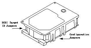
Figure 4-3 1.05 Gbyte Hard Disk Drive Jumper Locations
As shown above, there are two sets of jumper blocks that you need to check on for the 1.05 Gbyte drive:
To verify the target address jumpers:
Do not remove the drive bracket.
Refer to Table 4-1 if you do not have any SCSI devices attached to your system, such as external SCSI disk drives, tape drives, or CD-ROM drives.
Refer to Table 4-2 if you have SCSI devices attached to your system (such as external SCSI disk drives, tape drives, or CD-ROM drives), or if you added an additional SCSI bus to the system.
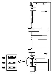
Figure 4-4 SCSI Target Address Jumper Settings
Table 4-1 Target Address Jumper Settings (SunOS 4.x)
--------------------------------------------------------------------


If you are connecting the SBus Expansion Sub        Target
system to one of the following computer systems:    Address
--------------------------------------------------------------------
SPARCstation 2 or 10 (or any other desktop system   0 or 2
with 2 disk drives)

SPARCstation IPX, IPC, LX, SPARCclassic (or         0 or 1 or 2
another desktop system with 1 disk drive)

SPARCsystem 630                                     0 or 2

--------------------------------------------------------------------
Note -
Before you set the device address jumpers on the disk drive, make sure
you check the device addresses already assigned for your system. Do not
assign two devices the same device address. If all available address settings
(0-3) are assigned for SCSI bus 0, you must add an SBus card which provides
another SCSI port (bus).
Table 4-2 Target Address Jumper Settings
-------------------------------------------


Disk drive jumper settings  Target Address
-------------------------------------------
No jumpers on A1-A2.        0* or

Jumper A0 only.             1* or

Jumper A1 only.             2* or

Jumper A0 and A1 only.      3*

Jumper A2                   4*

Jumper A2 and A0            5*

Jumper A2 and A1            6*

-------------------------------------------
Note - * Do not assign two devices the same target address.
To verify the configuration jumpers of the system unit:
If the settings are the same as those in the figure, leave them as they are.
If the settings are not the same, change them to match the settings in the figure. Use a needlenose pliers to install or remove jumpers.
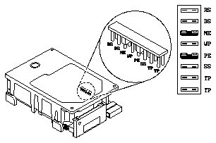
Figure 4-5 Configuration Jumper Settings
---------------------------------------


Acronym  Description
---------------------------------------
RS       (Reserved)

DS       Delayed Start

ME       Motor Enable (Remote Spin-up)

WP       Write Protect

PE       Parity Enable

SS       (Reserved)

TP       Term Power from Drive

TP       Term Power to SCSI Bus

---------------------------------------
Refer to Figure 4-6 for the location of the drives. If you are installing only one disk drive, install the drive in position 0 (near the side of the chassis). To install a drive, refer to the section, "Installing a Hard Disk Drive."
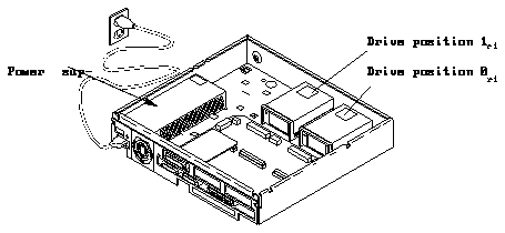
Figure 4-6 Drive Locations
To install a hard disk drive:
Fasten the bracket to the drive by inserting and tightening the four screws of the bracket into the bottom of the drive.
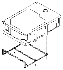
Figure 4-7 Attaching the Bracket to the Drive
The power and data cables are keyed so they will only fit one way.
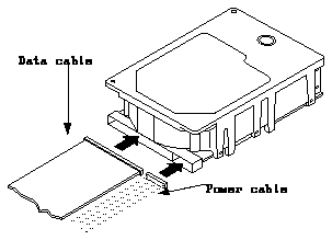
Figure 4-8 Connecting Data and Power Cables to the Drive
Align the four mounting tabs on the bottom of the mounting bracket with the slots in the bottom of the chassis.
You will hear a click when the two rear locking tabs seat firmly in their slots.
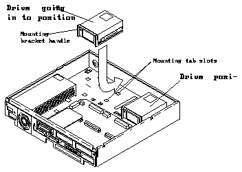
Figure 4-9 Installing the Disk Drive in an SBus Expansion Subsystem
For position 0 of the drive:
For position 1 of the drive:
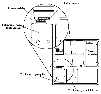
Figure 4-10 Connecting the Power and Data Cables
Refer to the section, "Replacing the SBus Expansion Subsystem Cover."
You must use the regulated SCSI terminator that was shipped with the drive and replace any non-regulated terminator.

You must use the regulated SCSI terminator that was shipped with the drive and replace any non-regulated terminator.
The installation procedure for replacing a drive requires that you remove the drive bracket, the data cable, and the power cable from the previously installed drive to install them on the replacement drive. A drive bracket and cables are not shipped with replacement drives.
Caution -

To remove a hard disk drive:
Refer to the section, "Removing the SBus Expansion Subsystem Cover."
Refer to the section, "Attaching a Wrist Strap."
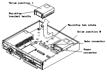
Figure 4-11 Removing a Hard Disk Drive
Place the old drive on an antistatic surface.
To replace the SBus Expansion Subsystem cover:
Gently guide the plastic tabs on the front of the cover into the tab slots on the front of the chassis and continue to hold the cover.
Caution -

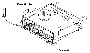
Figure 4-12 Replacing the SBus Expansion Subsystem Cover
You are now ready to power on the system.

To restore power to the system, turn on the power switches in the following order:
If you replaced a hard disk drive containing your operating system, you must install your operating system onto the new hard disk. Refer to the software manuals that were shipped with your operating system for complete instructions on all of the procedures you will need to perform on the drive.
Boot the system:
After you boot the operating system, log in at the login prompt.
For a newly installed peripheral device to work with a computer system, its device driver must be added or activated. Procedures for adding or activating a device driver differ among operating systems.
For example, if your system is running SunOS Version 4.x, you might need to modify the system kernel and make changes to the /dev directory by running the MAKEDEV command.
