
Make sure you read the Preface for the safety precautions and perform the tasks described in Chapter 1 before proceeding with this chapter.
Note - The 20 Gbyte 4 mm tape auto-loader is only supported for systems running on the Solaris 2.x operating system and above. If your Multi-Tape Backup Tray is installed in a system running an earlier version of the operating system, you must upgrade to the 2.x version before you can use the auto- loader.
Complete the procedures in the following sections to prepare the system for installing the auto-loader.
Refer to the Sun 56-Inch Data Center Expansion Cabinet Installation Manual (P/N 800-5936-xx) for instructions.
Grasp it underneath the front edge and pull it out to its fully-extended position. See Figure 3-1.

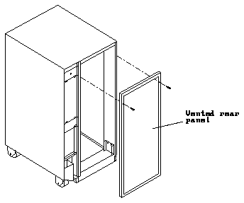
Figure 3-2 Removing the Vented Rear Panel
Note - If you are installing a 20 Gbyte 4 mm tape auto-loader in a tray that is not yet installed in the cabinet, go to Step 5.
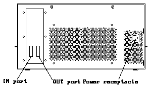
Do not remove the terminator from the OUT port.
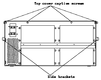
Figure 3-4 Removing the Tray Assembly in the Cabinet
There are three screws on each side and two each on the front and back of the tray.
Use the side brackets that were shipped with your auto-loader.
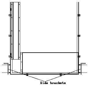
Figure 3-5 Side Brackets on a 56-Inch Expansion Cabinet
There are four locations for tape drives in the Multi-Tape Backup Tray. See Figure 3-6.
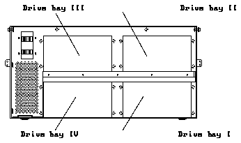
Figure 3-6 Drive Bays in the Multi-Tape Backup Tray
Firmly, but gently, pull the cable away from the connector at the rear of the tape drive. (For the power and SCSI ID cables, grasp each cable connector on both sides; for the SCSI data cable, use the strain relief tab.)
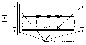
Figure 3-7 Drive Bay Mounting Screws
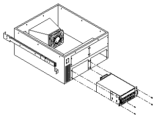
Figure 3-8 Removing the Drive from the Tray
Note - Make sure you have attached the mounting brackets to the auto-loader, as described in Chapter 1, "Preparing for Installation."
Auto-loaders must be installed in the drive bays in the following order:
See Figure 3-6 for the location of each drive bay. The drive bays are also labelled on the tray.
Use the 7 mm hex-head socket to remove the screws that secure the plate to the tray. See Figure 3-9.
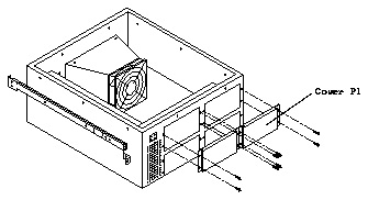
Figure 3-9 Removing the Cover Plate from the Drive Bay
If another cover plate is already secured to the top of the fan assembly, put the cover plate you just removed in a safe place.
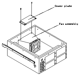
Figure 3-10 Attaching the Cover Plate to the Fan Assembly
Use the 7 mm hex-head socket.
Table 3-1 gives the correct DC harness connections for each auto-loader in the tray, and Figure 3-11 shows how the DC harness cables should be routed in the tray.
-------------------------------------


Drive Location  DC Harness Connector
-------------------------------------
I               P7

II              P8

III             P5

IV              P6

-------------------------------------
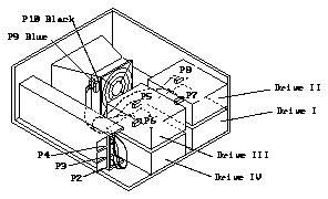
Figure 3-11 Connecting the DC Harness Cable
Table 3-2 gives the correct SCSI connections for each auto-loader in the tray, and Figure 3-12 shows how the SCSI data cables should be routed in the tray. The connector is keyed so that you cannot install the cable incorrectly.
------------------------------------


Drive Location  SCSI Data Connector
------------------------------------
I               P2

II              P3

III             P4

IV              P5

------------------------------------
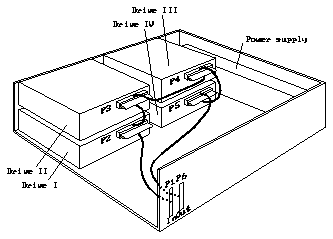
Figure 3-12 Connecting the SCSI Data Cable
Table 3-3 gives the correct SCSI ID connections for each auto-loader in the tray, and Figure 3-13 shows how the address cables should be routed in the tray.
----------------------------------


Drive Location  Address Connector
----------------------------------
I (J1)          P1

II (J2)         P2

III (J3)        P3

IV (J4)         P4

----------------------------------
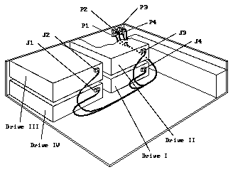
Figure 3-13 Connecting the Address Cable
Position the address cable so that the black wire is located at the lower right corner of the SCSI ID connector. See Figure 3-14.
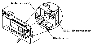
Figure 3-14 Positioning the Address Cable
The SCSI addresses for the auto-loaders in the Multi-Tape Backup Tray depend on the location of the drives in the tray. Table 3-4 shows the SCSI addresses for drives in a tray installed in a 56-Inch Data Center Expansion Cabinet.
Table 3-4 SCSI Addresses for the Auto-Loader
------------------------


Drive Bay  SCSI Address
------------------------
I          5

II         3

III        2

IV         4

------------------------
Figure 3-15 shows the four device select switches at the front of the Multi- Tape Backup Tray. Select the appropriate switch for the new drive, and press the buttons marked "+" or "-" until you see the correct address in the window.
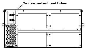
Figure 3-15 Device Select Switches on the Tray
Use the flat-head screwdriver to tighten the ten top cover captive screws.
The OUT port should have a terminator already installed.
Refer to the Sun 56-Inch Data Center Expansion Cabinet Installation Manual (P/N 800-5936-xx) for instructions on safely powering on the cabinet.
Caution -

To make sure that your system recognizes the newly-installed auto-loader, use the procedures in Appendix A, "Probing for SCSI Devices."
