
The disk tower 1000 is a compact system with the assemblies below:
Figure 6-1 shows the locations of each assembly in the system unit.
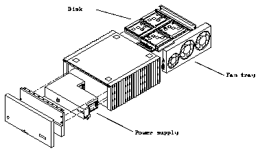
Figure 6-1
Subassembly Location
The fan tray is located on the chassis right side - viewed from the front. See
Figure 6-1.
6.1.1
Removal
1. Locate the fan tray from the back of the system.
The fan tray is on the left side of the chassis, viewed from the rear, and has
the power cord connector and the AC power switch.
2. Unplug the power cable from the fan tray.
3. Remove the two retaining screws that secure the fan tray to the chassis.
Set the screws aside for reinstallation.
See Figure 6-2.
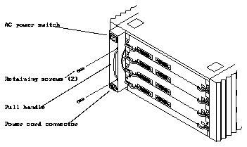
Figure 6-2
Fan Tray
4. Grasp the pull handle. Slowly and firmly slide the tray from the chassis.
6.1.2
Replacement
1. Slide the fan tray into the tray slot until you can hear and feel the
connector seat in the power supply connector.
2. Replace the retaining screws to secure the tray in place.
3. Reconnect the power cord and follow the power on procedures in
Chapter 4, "Powering Off and On."
The power supply is located in the lower front of the system behind the front
cover and EMI shield. See Figure 6-1.
6.2.1
Removal
1. Remove the front panel and EMI shield. See Chapter 5, "Internal Access."
2. Locate the power supply in the system lower front.
See Figure 6-1.
3. Loosen two captive retaining screws securing the supply to the chassis.
See Figure 6-3.
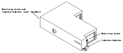
Figure 6-3
Power Supply
4. Rotate the injector/ejector levers down until they point straight out.
5. Firmly grasp the injector/ejector levers and pull toward you until you feel
the power supply disengage from the chassis.
6. Slide the power supply from the chassis.
Note -
Grasp the power supply firmly as soon as it is extended far enough to
do so. The power supply is heavy and could fall if not firmly gripped.
1. Slide the power supply into the chassis.
2. When the supply is halfway in, extend the injector/ejector levers out.
3. While holding the injector/ejector levers, slide the power supply into the
chassis until the levers engage the metal on the chassis.
4. Seat the power supply. Push both levers up simultaneously to maintain
insertion alignment until they are fully locked (up). Use care when doing
so avoid connector damage.
Caution -

Do not force the injector/ejector levers in if the power supply resists
seating in the connectors. Forcing the power supply in can damage connector
pins. Unseat the power supply, and retry by gently closing the injector/ejector
levers inward until fully seated.
5. Tighten the captive retaining screws.
6. Replace the EMI shield and the front panel.
7. Ensure the front panel key switch is in the ON position.
Note -
If necessary, borrow the key from the host SPARCserver 1000
keyswitch. Use this key to set the disk tower 1000 keyswitch to ON. Replace
the key in the SPARCserver 1000.
The backplane is located in the center of the chassis behind the front cover, EMI
shield and power supply. See Figure 6-1.
1. Remove the front panel and EMI shield. See Chapter 5, "Internal Access."
2. Remove the power supply as described in Section 6.2.
3. Remove any disk cards and air restrictor panels installed in the card cage.
4. Locate the backplane in the middle of the chassis.
See Figure 6-4.
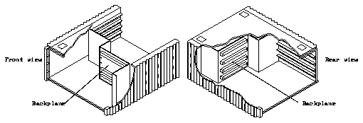
Figure 6-4
Backplane
5. From the system front, loosen ten screws securing the backplane in place.
See Figure 6-5.
6. Remove the backplane from the chassis.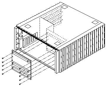
Figure 6-5
Removing the Backplane
6.3.2
Replacement
1. Slide the backplane into the chassis ensuring the side with three
connectors faces the front of the chassis.
2. Replace the ten screws to secure the backplane to the chassis.
3. Replace the power supply in the chassis as directed in Section 6.2.2,
"Replacement."
4. Replace disk cards and air restrictor boards removed at the beginning of
this procedure.
5. Replace the EMI shield and the front panel.


