
This chapter contains installation instructions for the SPARCstorage Array.
Caution -

Use a cushioned ESD mat to prevent breakage of parts on the
SPARCstorage Array controller. Also use an antistatic wrist strap.
Perform the following general steps. Refer to your system documentation for
specific instructions.
1. Halt the operating system.
2. Turn off the system power.
1. Power down the SPARCstorage Array.
The power switch is located on the back of the unit. See Figure 2-1.
Caution -

Do not unplug the AC cord. The cord provides a grounding path for
static electricity.
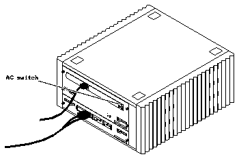
Figure 2-1
The AC Switch
2. Pull the interface connector to disconnect the cable.
See Figure 2-2. Pull only the connector, or the glass fibre in the cable may
break.
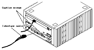
Figure 2-2
Array Controller Location
3. Loosen the two captive screws on the array controller.
See Figure 2-2.
4. Remove the array controller by swinging the ejector levers outward.
See Figure 2-3.
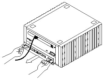
Figure 2-3
Removing the Array Controller
5. Turn the array controller upside down and place it on a cushioned ESD
mat.
The connector for the FC25/OM is on the bottom of the array controller.
6. Remove the filler panel from slot A.
See Figure 2-4. Lift the filler panel up to disengage the mounting pins.
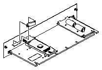
Figure 2-4
Removing the Filler Plate
1. Unwrap the FC25/OM module and pull out the two dust covers.
See Figure 2-5.
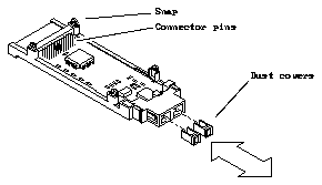
Figure 2-5
The Optical Module
2. Seat the optical module on the controller board, as follows:
a. Place the fibre connector through the opening in the array controller
back panel. See Figure 2-6.
b. Align the connector pins with the socket on the controller board.
c. Seat the FC25/OM on the socket.
d. Be sure the four snaps on the module are fully seated on the controller
board.
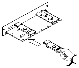
Figure 2-6
Installing the Second FC25/OM
3. Install the array controller in the SPARCstorage Array.
a. Move the ejector levers on the array controller to the open position.
b. Slide the array controller into the board guides until the controller
touches the backplane.
c. Use the ejection levers to seat the array controller connectors on the
backplane.
d. Tighten the two captive screws to secure the array controller to the
chassis.
4. Connect the Fibre Channel cables to the FC25/OM modules.
See Figure 2-7. The connectors are keyed to prevent upside-down insertion.
Connector B is to the left of connector A.
5. Route the new cable to the computer system.
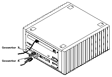
Figure 2-7
The Fibre Channel Connectors


