Chapter 1 Understanding the Sun Cluster Environment
This chapter provides an overview of the Sun Cluster product.
1.1 Sun Cluster Overview
The Sun Cluster system is a software environment that provides high availability (HA) support for data services and parallel database access on a cluster of servers (Sun Cluster servers). The Sun Cluster servers run the Solaris 2.6 or Solaris 7 operating environment, Sun Cluster framework software, disk volume management software, and HA data services or parallel database applications (OPS or XPS).
Sun Cluster framework software provides hardware and software failure detection, Sun Cluster system administration, system failover and automatic restart of data services in the event of a failure. Sun Cluster software includes a set of HA data services and an Application Programming Interface (API) that can be used to create other HA data services by integrating them with the Sun Cluster framework.
Shared disk architecture used with Sun Cluster parallel databases provide increased availability by allowing users to simultaneously access a single database through several cluster nodes. If a node fails, users can continue to access the data through another node without any significant delay.
The Sun Cluster system uses Solstice DiskSuite, Sun StorEdge Volume Manager (SSVM), or Cluster Volume Manager (CVM) software to administer multihost disks--disks that are accessible from multiple Sun Cluster servers. The volume management software provides disk mirroring, concatenation, striping, and hot sparing. SSVM and CVM also provide RAID5 capability.
The purpose of the Sun Cluster system is to avoid the loss of service by managing failures. This is accomplished by adding hardware redundancy and software monitoring and restart capabilities; these measures reduce single points of failure in the system. A single-point failure is the failure of a hardware or software component that causes the entire system to be inaccessible to client applications.
With redundant hardware, every hardware component has a backup that can take over for a failed component. The fault monitors regularly probe the Sun Cluster framework and the highly available data services, and quickly detect failures. In the case of HA data services, HA fault monitors respond to failures either by moving data services running on a failed node to another node, or, if the node has not failed, by attempting to restart the data services on the same node.
Sun Cluster configurations tolerate the following types of single-point failures:
-
Server operating environment failure because of a crash or a panic
-
Data service failure
-
Server hardware failure
-
Network interface failure
-
Disk media failure
1.2 Hardware Configuration Components
HA and parallel database configurations are composed of similar hardware and software components. The hardware components include:
-
Cluster nodes
-
Private interconnects
-
Public networks
-
Local disks
-
Multihost disks
-
Terminal Concentrator or System Service Processor (SSP)
-
Administrative Workstation
Details on all of these components are described in the following sections.
1.2.1 Cluster Nodes
Cluster nodes are the Sun EnterpriseTM servers that run data services and parallel database applications. Sun Cluster supports 2-, 3-, and 4-node clusters.
1.2.2 Cluster Interconnect
The cluster interconnect provides a reliable internode communication channel used for vital locking and heartbeat information. The interconnect is used for maintaining cluster availability, synchronization, and integrity. The cluster interconnect is composed of two private links. These links are redundant; only one is required for cluster operation. If all nodes are up and a single private interconnect is lost, cluster operation will continue. However, when a node joins the cluster, both private interconnects must be operational for the join to complete successfully.
Note -
By convention throughout this guide the network adapter interfaces hme1 and hme2 are shown as the cluster interconnect. Your interface names can vary depending on your hardware platform and your private network configuration. The requirement is that the two private interconnects do not share the same controller and thus cannot be disrupted by a single point of failure.
Clusters can use either the Scalable Coherent Interface (SCI) or Fast Ethernet as the private interconnect medium. However, support for mixed configurations (that is, both SCI and Ethernet private interconnects in the same cluster) is not supported.
1.2.2.1 The Switch Management Agent
The Switch Management Agent (SMA) is a cluster module that maintains communication channels over the private interconnect. It monitors the private interconnect and performs a failover of the logical adapter on the surviving private network if it detects a failure. In the case of more than one failure, SMA notifies the Cluster Membership Monitor which will take any action needed to change the cluster membership.
Clustered environments have different communication needs depending on the types of data services they support. Clusters providing only HA data services need only the heartbeat and minimal cluster configuration traffic over the private interconnect, and for these configurations Fast Ethernet is more than adequate. Clusters providing parallel database services send substantial amounts of traffic over the private interconnect. These applications benefit from the increased throughput of SCI.
SMA for SCI Clusters
The Scalable Coherent Interface (SCI) is a memory-based high-speed interconnect that enables sharing of memory among cluster nodes. The SCI private interconnect consists of Transmission Control Protocol/Internet Protocol (TCP/IP) network interfaces based on SCI.
Clusters of all sizes may be connected through a switch or hub. However, only two-node clusters may be connected point-to-point. The Switch Management Agent (SMA) software component manages sessions for the SCI links and switches.
There are three basic SCI topologies supported in Sun Cluster (Figure 1-1 and Figure 1-2):
-
Three- or four-node cluster that requires two SCI switches
-
Two-node cluster connected point-to-point
-
Two-node switched cluster (degenerate case of the four-node cluster that allows for future expansion of cluster nodes with minimal interruption)
Figure 1-1 SCI Cluster Topology for Four Nodes

Figure 1-2 SCI Cluster Topologies for Two Nodes

SMA for Ethernet Clusters
Clusters of all sizes may be connected through a switch or hub. However, only two-node clusters may be connected point-to-point. The Switch Management Agent (SMA) software component manages communications over the Ethernet switches or hubs.
There are three basic Ethernet topologies supported in Sun Cluster (Figure 1-3 and Figure 1-4):
-
Three- or four-node cluster that requires two Ethernet switches or hubs
-
Two-node point-to-point cluster
-
Two-node cluster with Ethernet switches or hubs (a degenerate case of the four-node cluster that allows for future expansion of cluster nodes with minimal interruption)
Figure 1-3 Ethernet Cluster Topology for Four Nodes
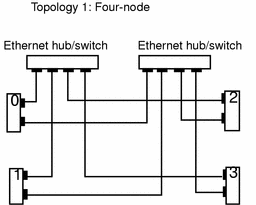
Figure 1-4 Ethernet Cluster Topologies for Two Nodes

1.2.3 /etc/nsswitch.conf File Entries
You must modify the /etc/nsswitch.conf file to ensure that "services," "group," and "hosts" lookups are always directed to the /etc files. This is done as part of the Sun Cluster installation described in Chapter 3, Installing and Configuring Sun Cluster Software.
The following shows an example /etc/nsswitch.conf file using NIS+ as the name service:
services: files nisplus |
This entry must be before other services entries. Refer to the nsswitch.conf(4) man page for more information.
You must update /etc/nsswitch.conf manually by using your favorite editor. You can use the Cluster Console to update all nodes at one time. Refer to the chapter on Sun Cluster administration tools in the Sun Cluster 2.2 System Administration Guide for more information on the Cluster Console.
1.2.4 Public Networks
Cluster access to a Sun cluster is achieved by connecting the cluster nodes to one or more public networks. You can have any number of public networks attached to your cluster nodes, but the public network(s) must connect to every node in the cluster, regardless of the cluster topology. Figure 1-5 shows a four-node configuration with a single public network (192.9.200). Each physical host has an IP address on the public network.
One public network is designated as the primary public network and other public networks are called secondary public networks. Each network is also referred to as a subnetwork or subnet. The physical network adapter (hme0) is also shown in Figure 1-5. By convention throughout this guide, hme0 is shown for the primary public network interface. This can vary depending on your hardware platform and your public network configuration.
Figure 1-5 Four-Node Cluster With a Single Public Network Connection
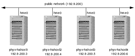
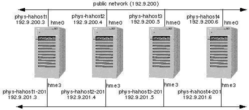
Figure 1-6 shows the same configuration with the addition of a second public network (192.9.201). An additional physical host name and IP address must be assigned on each Sun Cluster server for each additional public network.
The names by which physical hosts are known on the public network are their primary physical host names. The names by which physical hosts are known on a secondary public network are their secondary physical host names. In Figure 1-6 the primary physical host names are labeled phys-hahost[1-4]. The secondary physical host names are labeled phys-hahost[1-4]-201, where the suffix -201 identifies the network. Physical host naming conventions are described in more detail in Chapter 2, Planning the Configuration.
The network adapter hme3 is shown to be used by all nodes as the interface to the secondary public network. The adapter interface can be any suitable interface; hme3 is shown here as an example.
Figure 1-6 Four-Node Cluster With Two Public Networks
1.2.5 Local Disks
Each Sun Cluster server has one or more disks that are accessible only from that server. These are called local disks. They contain the Sun Cluster software environment and the Solaris operating environment.
Note -
Sun Cluster supports the capability to boot from a disk inside a multihost SPARCstorageTM Array (SSA) and does not require a private boot disk. The Sun Cluster software supports SSAs that have both local (private) and shared disks.
Figure 1-7 shows a two-node configuration including the local disks.
Local disks can be mirrored, but mirroring is not required. Refer to Chapter 2, Planning the Configuration, for a detailed discussion about mirroring the local disks.
1.2.6 Multihost Disks
In all Sun Cluster configurations, two or more nodes are physically connected to a set of shared, or multihost, disks. The shared disks are grouped across disk expansion units. Disk expansion units are the physical disk enclosures. Sun Cluster supports various disk expansion units: Sun StorEdgeTM MultiPack, Sun StorEdge A3000, and Sun StorEdge A5000 units, for example. Figure 1-7 shows two hosts, both physically connected to a set of disk expansion units. It is not required that all cluster nodes are physically connected to all disk expansion units.
In HA configurations, the multihost disks contain the data for highly available data services. A server can access data on a multihost disk when it is the current master of that disk. In the event of failure of one of the Sun Cluster servers, the data services fail over to another server in the cluster. At failover, the data services that were running on the failed node are started on another node without user intervention and with only minor service interruption. The system administrator can switch over data services manually at any time from one Sun Cluster server to another. Refer to "1.5.10 System Failover and Switchover", for more details on failover and switchover.
In parallel database configurations, the multihost disks contain the data used by the relational database application. Multiple servers access the multihost disk simultaneously. User processes are prevented from corrupting shared data by the Oracle UNIX Dynamic Lock Manager (DLM). If one server connected to a multihost disk fails, the cluster software recognizes the failure and routes user queries through one of the remaining servers.
All multihost disks with the exception of the Sun StorEdge A3000 (with RAID5) must be mirrored. Figure 1-7 shows a multihost disk configuration.
Figure 1-7 Local and Multihost Disks

1.2.7 Terminal Concentrator or System Service Processor and Administrative Workstation
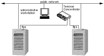
The Terminal Concentrator is a device used to connect all cluster node console serial ports to a single workstation. The Terminal Concentrator turns the console serial ports on cluster nodes into telnet-accessible devices. You can telnet to an address on the Terminal Concentrator, and see a boot-PROM-prompt capable console window.
The System Service Processor (SSP) provides console access for Sun Enterprise 10000 servers. The SSP is a Solaris workstation on an Ethernet network that is especially configured to support the Sun Enterprise 10000. The SSP is used as the administrative workstation for Sun Cluster configurations using the Sun Enterprise 10000. Using the Sun Enterprise 10000 Network Console feature, any workstation in the network can open a host console session.
The Cluster Console connects a telnet(1M) session to the SSP, allowing you to log into the SSP and start a netcon session to control the domain. Refer to your Sun Enterprise 10000 documentation for more information on the SSP.
The Terminal Concentrator and System Service Processor are used to shut down nodes in certain failure scenarios as part of the failure fencing process. See "1.3.4.1 Failure Fencing (SSVM and CVM)", for more details.
The administrative workstation is used to provide console interfaces from all of the nodes in the cluster. This can be any workstation capable of running a Cluster Console session.
See the Sun Cluster 2.2 System Administration Guide and the Terminal Concentrator documentation for further information on these interfaces.
Figure 1-8 Terminal Concentrator and Administrative Workstation
1.3 Quorum, Quorum Devices, and Failure Fencing
Quorum is a term that is often used in the clustering world, and it is a concept that comes into play quite often in distributed systems. Fundamentally speaking, it is no different from the quorum that is required in Congress to pass a piece of legislation --obtaining majority consensus to agree on an issue. The notion of what number constitutes an acceptable quorum can vary from issue to issue; some may require a simple 50+ percent of the votes, while others may require a 2/3-majority. Exactly the same notion applies to a set of communicating processes in a distributed system. To ensure the system operates effectively and to make critical decisions about the behavior of the system, the set of processes need to agree on the desired quorum and then try to obtain consensus on some underlying issue by communicating messages until a quorum is obtained.
In Sun Cluster, two different types of quorums are used.
-
The Cluster Membership Monitor (CMM) needs to obtain quorum about the set of cluster nodes that can participate in the cluster membership. The quorum is referred to as the CMM quorum, or cluster quorum.
-
The Cluster Configuration Database (CCD) needs to obtain quorum to elect a valid and consistent copy of the CCD.
1.3.1 CMM Quorum
The Sun Cluster and Solstice HA clustering products determined CMM quorum by different methods. In previous Sun Cluster releases including Sun Cluster 2.0 and 2.1, the cluster framework determined CMM quorum. In Solstice HA, quorum was determined by the volume manager, Solstice DiskSuite. Sun Cluster 2.2 is an integrated release based on both Sun Cluster 2.x and Solstice HA 1.x. In Sun Cluster 2.2, determining CMM quorum depends on the volume manager, Solstice DiskSuite, SSVM, or CVM. If Solstice DiskSuite is the volume manager, CMM quorum is determined by a quorum of metadevice state database replicas managed by Solstice DiskSuite. If SSVM or CVM are used as the volume manager, CMM quorum is determined by the cluster framework.
For Sun Cluster 2.2, CMM quorum is determined by the following:.
-
In clusters using SSVM and CVM as their volume manager, the cluster quorum is agreed upon based on the number of participating nodes and another independent device. In two-node clusters, a quorum device provides a third vote toward quorum. In greater-than-two-node clusters, an exclusive lock mechanism, a nodelock, is used to decide quorum if the cluster becomes split.
-
In clusters using Solstice DiskSuite as the volume manager, cluster quorum is agreed upon based on metadevice state database replicas or mediators. In configurations with at least three disk strings, the metadevice state database replicas can always determine whether a node is part of the cluster quorum. In two-node configurations with only two disk strings, the concept of a mediator was developed. Mediators work in a similar manner to the quorum device in SSVM and CVM. Refer to the chapter on mediators in the Sun Cluster 2.2 System Administration Guide for details.
It is necessary to determine cluster quorum when nodes join or leave the cluster and in the event that the cluster interconnect (the redundant private links between nodes) fails. In Solstice HA 1.x, cluster interconnect failure was considered a double failure and the software guaranteed to preserve data integrity, but did not guarantee that the cluster could continue without user intervention. Manual intervention for dual failures was part of the system design. It was determined to be the safest method to ensure data integrity in contrast to an automatic response that might preserve availability but compromise data integrity.
The Sun Cluster 2.x software attempted to preserve data integrity and to also maintain cluster availability without user intervention. To preserve cluster availability, Sun Cluster 2.x implemented several new processes. These included using quorum devices, and the Terminal Concentrator or System Service Processor. Note that since Solstice HA 1,x used Solstice DiskSuite to determine cluster quorum, in Sun Cluster 2.2, the volume manager is the primary factor in determining cluster quorum and what occurs when the cluster interconnect fails. The results of a cluster interconnect failure are described in "1.3.3 Quorum Devices (SSVM and CVM)".
1.3.2 CCD Quorum
The Cluster Configuration Database (CCD) needs to obtain quorum to elect a valid and consistent copy of the CCD. Refer to "1.5.6 Cluster Configuration Database", for an overview of the CCD.
Sun Cluster does not have a storage topology that guarantees direct access from all cluster nodes to underlying storage devices for all configurations. This precludes the possibility of using a single logical volume to store the CCD database, which would guarantee that updates would be propagated correctly across restarts of the cluster framework.The CCD communicates with its peers through the cluster interconnect, and this logical link is unavailable on nodes that are not cluster members. We will illustrate the CCD quorum requirement with a simple example.
Assume a three-node cluster consisting of nodes A, B, and C. Node A exits the cluster leaving B and C as the surviving cluster members. The CCD is updated and the updates are propagated to nodes B and C. Now, nodes B and C leave the cluster. Subsequently, node A is restarted. However, A does not have the most recent copy of the CCD database because it has no means of knowing the updates that happened on nodes B and C after it left the cluster membership the last time around. In fact, irrespective of which node is started first, it is not possible to determine in an unambiguous manner which node has the most recent copy of the CCD database. Only when all three nodes are restarted is there sufficient information to determine the most recent copy of the CCD.If a valid CCD could not be elected, all query or update operations on the CCD would fail with an invalid CCD error. In practice, starting all cluster nodes before determining a valid copy of the CCD is too restrictive a condition.
This condition can be relaxed by imposing a restriction on the update operation. If N is the number of currently configured nodes in the cluster, at least floor(n/2)+1 [floor(n) = n, if (n modulo 1 = 0), = n - (n modulo 1), if (n modulo 1 != 0)] nodes must be up for updates to be propagated. In this case, it is sufficient for ceiling(n/2) [ceiling(n) = n, if (n modulo 1 = 0), = n +1 - (n modulo 1), if (n modulo 1 != 0)] identical copies to be present to elect a valid database on a cluster restart. The valid CCD is then propagated to all cluster nodes that do not already have it.
Note that even if the CCD is invalid, a node is allowed to join the cluster. However, the CCD can neither be updated or queried in this state. This implies that all components of the cluster framework that rely on the CCD remain in a dysfunctional state. In particular, logical hosts cannot be mastered and data services cannot be activated in this state. The CCD is enabled only after sufficient number of nodes join the cluster for quorum to be reached. Alternatively, an administrator can restore the CCD database with the maximum CCD generation number.
CCD quorum problems can be avoided if at least one or more nodes stay up during a reconfiguration. In this case, the valid copy on any of these nodes will be propagated to the newly joining nodes. Another alternative is to ensure that the cluster is started up on the node that has the most recent copy of the CCD database. Nevertheless, it is quite possible that after a system crash while a database update was in progress, the recovery algorithm finds inconsistent CCD copies. In such cases, it is the responsibility of the administrator to restore the database using the ccdadm(1M) restore option. The CCD also provides a checkpoint facility to backup the current contents of the database. It is good practice to make a backup copy of the CCD database after any change to system configuration. The backup copy can then be used to subsequently restore the database. The CCD is quite small compared to conventional relational databases and the backup and restore operations take no more than a few seconds to complete.
1.3.2.1 CCD Quorum in Two-Node Clusters
In the case of two-node clusters, the previously discussed quorum majority rule would require both nodes to be cluster members for updates to succeed, which is too restrictive. On the other hand, if updates are allowed in this configuration while only one node is up, the database will have to be manually made consistent before restarting the cluster. This can be accomplished by either restarting the node that has the most recent copy first, or restoring the database with the ccdadm(1M) restore operation after both nodes have joined. In the latter case, even though both nodes will be able to join the cluster membership, the CCD will be in an invalid state until the restore operation is complete.
This problem is solved by configuring persistent storage for the database on a shared disk device. The shared copy is used only when a single node is active. When the second node joins, the shared CCD copy is copied into the local copy on each node.
Whenever one of the nodes leave, the shared copy is reactivated by copying the local CCD into the shared copy. This enables updates only when a single node is in the cluster membership and also ensures reliable propagation of updates across cluster restarts.
The downside of using a shared storage device for the shared copy of the CCD is that two disks need to be allocated exclusively for this purpose, because the volume manager precludes these disks from being used for any other purpose. The usage of the two disks can be avoided if application downtime caused by the procedural limitations described above are understood and can be tolerated in a production environment.
Similar to the Sun Cluster 2.2 integration issues with the CMM quorum, a shared CCD is not supported in all Sun Cluster configurations. If Solstice DiskSuite is the volume manager, the shared CCD is not supported. Because the shared CCD is only used when one node is active, the failure addressed by the shared CCD is not common.
1.3.3 Quorum Devices (SSVM and CVM)
In certain cases--for example, in a two-node cluster when both cluster interconnects fail and both cluster nodes are still members--Sun Cluster needs assistance from a hardware device to solve the problem of cluster quorum. This device is called the quorum device.
Quorum devices must be used in clusters running either Sun StorEdge Volume Manager (SSVM) or Cluster Volume Manager (CVM) as the volume manager, regardless of the number of cluster nodes. Solstice DiskSuite assures cluster quorum through the use of its own metadevice state database replicas, and as such, does not need a quorum device. Quorum devices are neither required nor supported in Solstice DiskSuite configurations. When you install a cluster using Solstice DiskSuite, the scinstall(1M) program will not ask for, or accept a quorum device.
The quorum device is merely a disk or a controller which is specified during the cluster installation procedure by using the scinstall(1M) command. The quorum device is a logical concept; there is nothing special about the specific piece of hardware chosen as the quorum device. However, the quorum device must be in its own disk group to be imported and exported independently. SSVM does not allow a portion of a disk to be in a separate disk group, so an entire disk and its plex (mirror) are required for the quorum device. Since you cannot be sure which node will have the quorum device imported at any time, it cannot usefully store data besides the data needed for the quorum.
A quorum device ensures that at any point in time only one node can update the multihost disks that are shared between nodes. The quorum device comes into use if the cluster interconnect is lost between nodes. Each node (or set of nodes in a greater than two-node cluster) should not attempt to update shared data unless it can establish that it is part of the majority quorum. The nodes take a vote, or quorum, to decide which nodes remain in the cluster. Each node determines how many other nodes it can communicate with. If it can communicate with more than half of the cluster, then it is in the majority quorum and is allowed to remain a cluster member. If it is not in the majority quorum, the node aborts from the cluster.
The quorum device acts as the "third vote" to prevent a tie. For example, in a two-node cluster, if the cluster interconnect is lost, each node will "race" to reserve the quorum device. Figure 1-9 shows a two-node cluster with a quorum device located in one of the multihost disk enclosures.
Figure 1-9 Two-node Cluster with Quorum Device
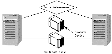
The node that reserves the quorum device then has two votes toward quorum versus the remaining node that has only one vote. The node with the quorum will then start its own cluster (mastering the multihost disks) and the other node will abort.
Before each cluster reconfiguration, the set of nodes and the quorum device vote to approve the new system configuration. Reconfiguration proceeds only if a majority quorum is reached. After a reconfiguration, a node remains in the cluster only if it is part of the majority partition.
Note -
In greater than two-node clusters, each set of nodes that share access to multihost disks must be configured to use a quorum device.
The concept of quorum device changes somewhat in greater than two-node clusters. If there is an even split for nodes that do not share a quorum device--referred to as a "split-brain" partition--you must be able to decide which set of nodes will become a new cluster and which set will abort. This situation is not handed by the quorum device. Instead, as part of the installation process, when you configure the quorum device(s), you are asked questions that determine what will happen when such a partition occurs. One of two events occurs in this partition situation depending on whether you requested to have the cluster software automatically select the new cluster membership or whether you specified manual intervention.
-
Automatic selection - If, during installation, you choose select, then the software automatically selects which subset is aborted based on either the Lowest Nodeid or the Highest Nodeid. If you chose the Lowest Nodeid, then the subset containing the node with the lowest node ID value automatically becomes the new cluster. If you chose the Highest Nodeid, then the subset containing the node with the highest node ID value automatically becomes the new cluster. You must manually abort all other subsets.
-
Manual intervention - At the time of the partition, the system prompts you to choose the new cluster.
For example, consider a four-node cluster (that might or might not share a storage device common to all nodes) where a network failure results in node 0 and 1 communicating with each other and nodes 2 and 3 communicating with each other. In this situation, the automatic or manual decision of quorum would be used. The cluster monitor software is quite intelligent. It tries to determine on its own which nodes should be cluster members and which should not. It resorts to the quorum device to break a tie or the manual and automatic selection of cluster domains only in extreme situations.
Note -
The failure of a quorum device is similar to the failure of a node in a two-node cluster.
The quorum device on its own cannot account for all scenarios where a decision must be made on cluster membership. For example, consider a fully operational three-node cluster, where all of the nodes share access to the multihost disks, such as the Sun StorEdge A5000. If one node aborts or loses both cluster interconnects, and the other two nodes are still able to communicate to each other, the two remaining nodes do not have to reserve the quorum device to break a tie. Instead, the majority voting that comes into play (two votes out of three) determines that the two nodes that can communicate with each other can form the cluster. However, the two nodes that form the cluster must still prevent the crashed or hung node from coming back online and corrupting the shared data. They do this by using a technique called failure fencing, as described in "1.3.4 Failure Fencing ".
1.3.4 Failure Fencing
In any clustering system, once a node is no longer in the cluster, it must be prevented from continuing to write to the multihost disks. Otherwise, data corruption could ensue. The surviving nodes of the cluster need to be able to start reading from and writing to the multihost disk. If the node that is no longer in the cluster is continuing to write to the multihost disk, its writes would confuse and ultimately corrupt the updates that the surviving nodes are performing.
Preventing a node that is no longer in the cluster from writing to the disk is called failure fencing. Failure fencing is very important for ensuring data integrity by preventing an isolated node from coming up in its own partition as a separate cluster when the actual cluster exists in a different partition.
It is very important to prevent the faulty node from performing I/O as the two cluster nodes now have very different views. The faulty node's cluster view includes both cluster members (because it has not been reconfigured), while the surviving node's cluster view consists of a one-node cluster (itself).
In a two-node cluster, if one node hangs or fails, the other node detects the missing heartbeats from the faulty node and reconfigures itself to become the sole cluster member. Part of this reconfiguration involves fencing the shared devices to prevent it from performing I/O on the multihost disks. In all Sun Cluster configurations with only two-nodes, this is accomplished through the use of SCSI-2 reservations on the multihost disks. The surviving node reserves the disks and prevents the failed node from performing I/O on the reserved disks. The semantics of the SCSI-2 reservation is that it is atomic in nature and if two nodes simultaneously attempt to reserve the device, one is guaranteed to succeed and the other guaranteed to fail.
1.3.4.1 Failure Fencing (SSVM and CVM)
Failure fencing is done differently depending on the cluster topology. The simplest case is a two-node cluster.
Failure Fencing Two-Node Clusters
In a two-node cluster, the quorum device determines which node remains in the cluster and the failed node is prevented from starting its own cluster because it cannot reserve the quorum device. SCSI-2 reservation is used to fence a failed node and prevent it from updating the multihost disks.
Failure Fencing Greater Than Two-Node Clusters
The difficulty with the SCSI-2 reservation model used in two-node clusters is that the SCSI reservations are host-specific. If a host has issued reservations on shared devices, it effectively shuts out every other node that can access the device, faulty or not. Consequently, this model breaks down when more than two nodes are connected to the multihost disks in a shared disk environment such as OPS.
For example, if one node hangs in a three-node cluster, the other two nodes reconfigure. However, neither of the surviving nodes can issue SCSI reservations to protect the underlying shared devices from the faulty node, as this action also shuts out the other surviving node. But without the reservations, the faulty node might "wake up" and issue I/O to the shared devices, despite the fact that its view of the cluster is no longer current.
Consider a four-node cluster with storage devices directly accessible from all the cluster nodes. If one node hangs, and the other three nodes reconfigure, none of them can issue the reservations to protect the underlying devices from the faulty node, as the reservations will also prevent some of the valid cluster members from issuing any I/O to the devices. But without the reservations, we have the real danger of the faulty node "waking up" and issuing I/O to shared devices despite the fact that its view of the cluster is no longer current.
Now consider the problem of split-brain situations. In the case of a four-node cluster, a variety of interconnect failures are possible. We will define a partition as a set of cluster nodes where each node can communicate with every other member within that partition, but not with any other cluster node that is outside the partition. There can be situations where, due to interconnect failures, two partitions are formed with two nodes in one partition and two nodes in the other partition, or with three nodes in one partition and one node in the other partition. Or there can even be cases where a four-node cluster can degenerate into four different partitions with one node in each partition. In all such cases, Sun Cluster attempts to arrive at a consistent distributed consensus on which partition should stay up and which partition should abort. Consider the following two cases.
Case 1. Two partitions with two nodes in each partition. As in the case of the one-one split in the case of a two-node cluster, the CMMs in either partition do not have quorum to conclude decisively which partition should stay up and which partition should abort. To meet the goals of data integrity and high availability, both partitions should not stay up and both partitions should not go down. As in the case of a two-node cluster, is it possible to adjudicate by means of an external device (the quorum disk) A designated node in each partition can race for the reservation on the designated quorum device, and whichever partition wins would be declared the winner. However, the node that successfully obtains the reservation on the quorum device shuts out the other node in its own partition from accessing the device due to the nature of the SCSI-2 reservation. because the quorum device contains useful data, this is not a desirable thing to do.
Case 2. Two partitions with three nodes in one partition and one node in the other partition. Even though the majority partition in this case has adequate quorum, the crux of the problem here is that the single isolated node has no idea what happened to the other three nodes. Perhaps they formed a valid cluster and this node should abort. But perhaps they did not; perhaps all three nodes did really fail for some reason. In this case, the single isolated node must stay up to maintain availability. With total loss of communication and without an external device to mediate, it is impossible to decide. Racing for the reservation of a configured external quorum device leads to a situation worse than in case 1. If one of the nodes in the majority partition reserves the quorum device, it shuts out the other two nodes in its own partition from accessing the device. But what is worse is that if the single isolated node wins the race for the reservation, it may lead to the loss of three potentially healthy nodes from the cluster. Once again, the disk reservation solution does not work well.
The inability to use the disk reservation technique also renders the system vulnerable to the formation of multiple independent clusters, each in its own isolated partition, in the presence of interconnect failures and operator errors. Consider case 2 above: Assume that the CMMs or some external entity somehow decides that the three nodes in the majority partition should stay up and the single isolated node should abort. Assume at some later point in time, the administrator now attempts to start up the aborted node without repairing the interconnect. The node would still be unable to communicate with any of the surviving members, and thinking it is the only node in the cluster, attempt to reserve the quorum device. It would succeed because there are no quorum reservations in effect, due to the reasons elucidated above, and form its own independent cluster with itself as the sole cluster member.
Therefore, the simple quorum reservation scheme is unusable for three and four node clusters with storage devices directly accessible from all nodes. We need new techniques to solve the following three problems:
-
How to resolve all split-brain situations in three and four node clusters?
-
How do we failure fence faulty nodes from shared devices?
-
How do we prevent isolated partitions from forming multiple independent clusters?
To solve the different types of split-brain situations in three and four node clusters, a combination of heuristics and manual intervention is used, with the caveat that operator error during the manual intervention phase can destroy the integrity of the cluster. In "1.3.3 Quorum Devices (SSVM and CVM)", we discussed the policies that can be specified to determine what occurs in the event of a cluster partition for greater than two node clusters. If you choose the interventionist policy, the CMMs on all partitions will suspend all cluster operations in each partition waiting for manual operator input as to which partition is to continue to form a valid cluster and which partition should abort. It is the operator's responsibility to let a desired partition to continue and to abort all other partitions. Allowing more than one partition to form a valid cluster can result in irretrievable data corruption.
If you choose a pre-deterministic policy, a preferred node (either the highest or lowest node id in the cluster) is requested, and when a split-brain situation occurs, the partition containing the preferred node will automatically become the new cluster if it is able to do so. All other partitions must be manually aborted by operator intervention. The selected quorum device is used solely to break the tie in the case of a split-brain for two-node clusters. Note that this situation can happen even in a configured four-node cluster, where only two cluster members are active when a split-brain situation occurs. The quorum device still plays a role, but in a much more limited capacity.
Once a partition has been selected to stay up, the next question is how to effectively protect the data from other partitions that should have aborted. Even though we require the operator to abort all other partitions, the command to abort the partition may not succeed immediately, and without an effective failure fencing mechanism, there is always the danger of hung nodes suddenly "waking up" and issuing pending I/O to shared devices before processing the abort request. In this case, the faulty nodes are reset before a valid cluster is formed in some partition.
To prevent a failed node from "waking up" and issuing I/O to the multihost disks, the faulty node is forcefully terminated by one of the surviving nodes, and dropped down to the OpenBoot PROM via the Terminal Concentrator or System Service Processor (Sun Enterprise 10000 systems), and the hung image of the operating system is terminated. This terminal operation prevents you from accidentally resuming a system by typing go at the Boot PROM. The surviving cluster members wait for a positive acknowledgment from the termination operation before proceeding with the cluster reconfiguration process.
If there is no response to the termination command, then the hardware power sequencer (if present) is tripped to power cycle the faulty node. If tripping is not successful, then the system displays the following message requesting information to continue cluster reconfiguration:
/opt/SUNWcluster/bin/scadmin continuepartition localnode clustername \007*** ISSUE ABORTPARTITION OR CONTINUEPARTITION *** You must ensure that the unreachable node no longer has access to the shared data. You may allow the proposed cluster to form after you have ensured that the unreachable node has aborted or is down. Proposed cluster partition: |
Note -
You should ensure that the faulty node has been successfully terminated before issuing the scadmin continuepartition command on the surviving nodes.
Partitioned, isolated, and terminated nodes do eventually boot up, and if due to some oversight, if the administrator tries to join the node into the cluster without repairing the interconnects, we must prevent this node from forming a valid cluster partition of its own if the node is unable to communicate with the existing cluster.
Assume a case where two partitions are formed with three nodes in one partition and one node in the other partition. A designated node in the majority partition terminates the isolated node and the three nodes form a valid cluster in their own partition. The isolated node, on booting up, tries to form a cluster of its own due to an administrator running the startcluster(1M) command and replying in the affirmative when asked for confirmation. Because the isolated node believes it is the only node in the cluster, it tries to reserve the quorum device and actually succeeds in doing so, because there are three nodes in the valid partition and none of them can reserve the quorum device without locking the others out.
To resolve this problem, a new concept is needed, a nodelock. For this concept, a designated node in the cluster membership opens a telnet(1) session to an unused port in the Terminal Concentrator as part of its cluster reconfiguration and keeps this session alive as long as it is a cluster member. If this node were to leave the membership, the nodelock is passed on to one of the remaining cluster members. In the above example, if the isolated node were to try to form its own cluster, it would try to acquire this lock and fail, because one of the nodes in the existing membership (in the other partition) would be holding this lock. If one of the valid cluster members is unable to acquire this lock for some reason, it would not be considered a fatal, but would be logged as an error requiring immediate attention. The locking facility should be considered as a safety feature rather than a mechanism critical to the operation of the cluster, and its failure should not be considered catastrophic. In order to speedily detect faults in this area, monitoring processes in the Sun Cluster framework monitor whether the Terminal Concentrator is accessible from the cluster nodes.
1.3.4.2 Failure Fencing (Solstice DiskSuite)
In Sun Cluster configurations using Solstice DiskSuite as the volume manager, it is Solstice DiskSuite itself that determines cluster quorum and provides failure fencing. There is no distinction between different cluster topologies for failure fencing. That is, two-node and greater than two-node clusters are treated identically. This is possible for two reasons:
-
Unlike the situation with Cluster Volume Manager, there is no concept of shared disks in the HA environment. At most, only one node can master a diskset at any given time. This precludes the situation where more than one node would need to access the diskset after a node fails.
-
The split-brain situation, where the cluster interconnect fails is viewed as a double failure (both private links have failed). In the event of a split-brain situation, the guarantee is that data integrity will be maintained. There is no guarantee that the cluster will be able to continue without user intervention. For example, in a three-node cluster where all nodes are attached to the diskset, and split brain develops, it is possible that one node will crash, two nodes will crash, or all three nodes will crash. This algorithm has been shown to have higher actual availability than any algorithm employing a quorum device.
Disk fencing is accomplished in the following manner.
-
After a node is removed from the cluster, a remaining node does a SCSI reserve of the disk. After this, other nodes--including the one no longer in the cluster--are prevented by the disk itself to read or write to the disk. The disk will return a Reservation_Conflict error to the read or write command. In Solstice DiskSuite configurations, the SCSI reserve is accomplished by issuing the Sun multihost ioctl MHIOCTKOWN.
-
Nodes that are in the cluster continuously enable the MHIOCENFAILFAST ioctl for the disks that they are accessing. This ioctl is a directive to the disk driver, giving the node the capability to panic itself if it cannot access the disk due to the disk being reserved by some other node. The MHIOCENFAILFAST ioctl causes the driver to check the error return from every read and write that this node issues to the disk for the Reservation_Conflict error code, and it also periodically, in background, issues a test operation to the disk to check for Reservation_Conflict. Both the foreground and the background control flow paths will panic should Reservation_Conflict be returned.
-
The MHIOCENFAILFAST ioctl is not specific to dual-hosted disks. If the node that has enabled the MHIOCENFAILFAST for a disk loses access to that disk due to another node reserving the disk (by SCSI-2 exclusive reserve), the node panics.
This solution to disk fencing relies on the SCSI-2 concept of disk reservation, which requires that a disk be reserved by exactly one single node.
For Solstice DiskSuite configurations, the installation program scinstall(1M) does not prompt for a quorum device, a node preference, or to select a failure fencing policy as is done in SSVM and CVM configurations. When Solstice DiskSuite is specified as the volume manager, you cannot configure direct-attach devices, that is, devices that directly attach to more than two nodes. Disks can only be connected to pairs of nodes.
Note -
Although the scconf(1M) command allows you to specify the +D flag to enable configuring direct-attach devices, you should not do so in Solstice DiskSuite configurations.
1.3.5 Preventing Partitioned Clusters (SSVM and CVM)
Two-Node Clusters
If lost interconnects occur in a two-node cluster, both nodes attempt to start the cluster reconfiguration process with only the local node in the cluster membership (because each has lost the heartbeat from the other node). The first node that succeeds in reserving the configured quorum device remains as the sole surviving member of the cluster. The node that failed to reserve the quorum device aborts.
If you try to start up the aborted node without repairing the faulty interconnect, the aborted node (which is still unable to contact the surviving node) attempts to reserve the quorum device, because it sees itself as the only node in the cluster. This attempt will fail because the reservation on the quorum device is held by the other node. This action effectively prevents a partitioned node from forming its own cluster.
Three- or Four-Node Clusters
If a node drops out of a four-node cluster as a result of a reset issued via the terminal concentrator (TC), the surviving cluster nodes are unable to reserve the quorum device, since the reservation by any other node prevents the two healthy nodes from accessing the device. However, if you erroneously ran the scadmin startcluster command on the partitioned node, the partitioned node would form its own cluster, since it is unable to communicate with any other node. There are no quorum reservations in effect to prevent it from forming its own cluster.
Instead of the quorum scheme, Sun Cluster resorts to a cluster-wide lock (nodelock) mechanism. An unused port in the TC of the cluster, or the SSP, is used. (Multiple TCs are used for campus-wide clusters.) During installation, you choose the TC or SSP for this node-locking mechanism. This information is stored in the CCD. One of the cluster members always holds this lock for the lifetime of a cluster activation; that is, from the time the first node successfully forms a new cluster until the last node leaves the cluster. If the node holding the lock fails, the lock is automatically moved to another node.
The only function of the nodelock is to prevent operator error from starting a new cluster in a split-brain scenario.
Note -
The first node joining the cluster aborts if it is unable to obtain this lock. However, node failures or aborts do not occur if the second and subsequent nodes of the cluster are unable to obtain this lock.
Node locking functions in this way:
-
If the first node to form a new cluster is unable to acquire this lock, it aborts with the following message:
[SUNWcluster.reconf.nodelock.4002] $clustname Failed to obtain
NodeLock status = ??
-
If the first node to form a new cluster acquires this lock, the following message is displayed:
[SUNWcluster.reconf.nodelock.1000] $clustname Obtained Nodelock
-
If one of the current nodes in a cluster is unable to acquire this lock during the course of a reconfiguration, an error message is logged on the system console:
[SUNWcluster.reconf.nodelock.3004] $clustname WARNING: Failed to Force obtain
NodeLock status = ??
 Caution -
 This message warns you that the lock could not be acquired. You need to diagnose and fix this error as soon as possible to prevent possible future problems.
-
If a partitioned node tries to form its own cluster (by using the scadmin startcluster command), it is unable to acquire the cluster lock if the cluster is active in some other partition. Failure to acquire this lock causes this node to abort.
1.4 Configurations Supported by Sun Cluster
A cluster is composed of a set of physical hosts, or nodes. Throughout the Sun Cluster documentation, cluster nodes also are referred to as Sun Cluster servers.
The Sun Cluster hardware configuration supports symmetric, asymmetric, clustered pairs, ring, N+1 (star), or N to N (scalable) topologies. Each of these is described in detail later in this chapter.
A symmetric configuration has only two nodes. Both servers are configured identically and, generally, both provide data services during normal operation. See Figure 1-12.
A two-node configuration where one server operates as the hot-standby server for the other is referred to as an asymmetric configuration. This configuration is treated as an N+1 configuration where N=1.
Clustered pairs are two pairs of Sun Cluster nodes operating under a single cluster administrative framework. See Figure 1-13.
The ring configuration allows for one primary and one backup server to be specified for each set of data services. All disk storage is dual-hosted and physically attached to exactly two cluster nodes. The nodes and storage are connected alternately, in a ring. This is ideal for configuring multiple online highly available data services. See Figure 1-14.
An N+1 or star configuration is composed of two or more nodes. One node in the N+1 configuration (the +1 node) might be configured to be inactive until there is a failure of another node. In this configuration, the +1 node operates as a "hot-standby." The remaining nodes are "active" in normal operation. The examples in this chapter assume that the hot-standby node is not running data services in normal operation. However there is no requirement that the +1 node not run data services in normal operation. See Figure 1-15.
An N to N, or scalable configuration has all servers directly connected to a set of shared disks. This is the most flexible configuration because data services can fail over to any of the other servers. See Figure 1-16.
1.4.1 High Availability and Parallel Database Configurations
Sun Cluster supports HA data service and parallel database configurations. HA and parallel databases can also be combined within a single cluster, with some restrictions.
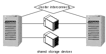
Data services in an HA configuration are made highly available by having multiple hosts connected to the same physical disk enclosure. The status of each host is monitored over private interconnects. If one of the hosts fails, another host connected to the same shared storage device can take over the data service work previously done by the failed host. Figure 1-10 shows an example of a highly available data service configuration.
Figure 1-10 Highly Available Data Services Configuration
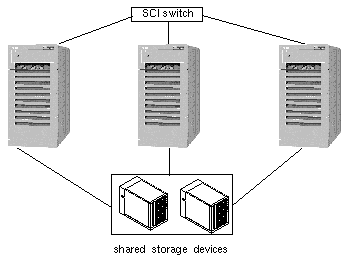
Oracle Parallel Server (OPS) enables a relational database to be highly available by enabling multiple hosts to access the same data on shared storage devices. Traffic to the shared disk enclosures is controlled by a DLM that prevents two processes from accessing the same data at the same time. High availability is attained by redirecting database access traffic from a failed host to one of the remaining nodes. Figure 1-11 shows an example of a highly available OPS configuration. The private interconnect can be either the Scalable Coherent Interface (SCI) or Fast Ethernet.
Figure 1-11 OPS Database Configuration
The Informix-Online XPS parallel database permits parallel access by partitioning the relational database across shared storage devices. Multiple host processes can access the same database simultaneously provided they do not access data stored in the same partition. Access to a particular partition is through a single host, so if that host fails, no access is possible to that partition of data. For this reason, Informix-Online XPS is a parallel database, but cannot be configured to be highly available in a Sun Cluster.
1.4.2 Symmetric and Asymmetric Configurations
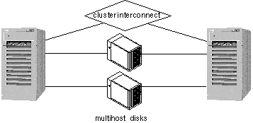
Symmetric and asymmetric HA configuration, by definition, consists of exactly two nodes. Highly available data services run on one or both nodes. Figure 1-12 shows a two-node configuration. This example configuration consists of two active nodes (phys-hahost1 and phys-hahost2) that are referred to as siblings.
Both nodes are physically connected to a set of multihost disks.
Figure 1-12 Two-node Configuration
1.4.3 Clustered Pairs Configuration
The clustered pairs configuration is a variation on the symmetric configuration. In this configuration, there are two pairs of servers, with each pair operating independently. However, all of the servers are connected by the private interconnects and are under control of the Sun Cluster software.
Figure 1-13 Clustered Pairs Configuration
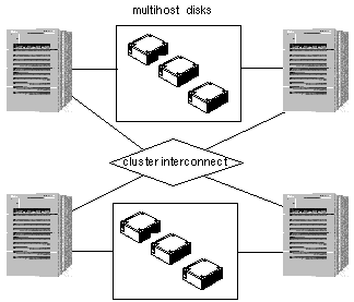
Clustered pairs can be configured so that you can run a parallel database application on one pair and HA data services on the other. Failover is only possible across a pair.
1.4.4 Ring Configuration
The ring configuration allows for one primary and one backup server to be specified for each set of data services. The backup for a given data service is a node adjacent to the primary. All disk storage is dual-hosted and physically attached to exactly two cluster nodes. The nodes and storage are connected alternately, in a ring. All nodes can be actively running applications. Each node is both a primary for one set of data services and a backup for another set. Figure 1-14 shows a four-node ring configuration.
Figure 1-14 Ring Configuration
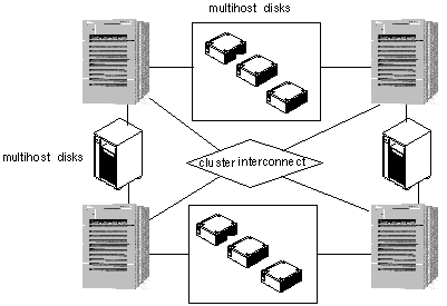
Note -
A restriction to the ring configuration is that you cannot run multiple RDBMS data services on the same node.
1.4.5 N+1 Configuration (Star)
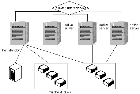
An N+1 or star configuration includes some number of active servers and one hot-standby server. The active servers and hot-standby server do not have to be configured identically. Figure 1-15 shows an N+1 configuration. The active servers provide on-going data services while the hot-standby server waits for one or more of the active servers to fail. The hot-standby server is the only server in the configuration that has physical disk connections to all disk expansion units.
In the event of a failure of one active server, the data services from the failed server fail over to the hot-standby server. The hot-standby server then continues to provide data services until the data services are switched over manually to the original active server.
The hot-standby server need not be idle while waiting for another Sun Cluster server to fail. However, the hot-standby server should always have enough excess CPU capacity to handle the load should one of the active servers fail.
Figure 1-15 N+1 Configuration
1.4.6 N to N Configuration (Scalable)
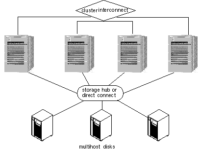
An N to N or scalable configuration has all servers physically connected to all multihost disks. Data services can fail over from one node to a backup, to another backup, a feature known as cascading failover.
This is the highest redundancy configuration because data services can fail over to up to three other nodes.
Figure 1-16 N to N Configuration
1.4.7 Campus Clustering
Sun Cluster features campus clustering, a cluster configuration that provides geographic site separation and enables recovery from certain types of failures, which is localized to a part of the campus.
The servers and storage devices may be physically located in the same server room, or geographically distributed across multiple sites. Geographical distribution improves protection of data from catastrophic failures, such as a fire, and thus improves overall data service availability.
For additional information on campus clustering, contact your local Sun sales representative.
1.5 Software Configuration Components
Sun Cluster includes the following software components:
-
Cluster framework
-
Data services
Associated with these software components are the following logical components:
-
Logical hosts
-
Disk groups
These components are described in the following sections.
1.5.1 Cluster Framework
Figure 1-17 shows the approximate layering of the various components that constitute the framework required to support HA data services in Sun Cluster. This diagram does not illustrate the relationship between the various components of Sun Cluster. The innermost core consists of the Cluster Membership Monitor (CMM), which keeps track of the current cluster membership. Whenever nodes leave or rejoin the cluster, the CMM on the cluster nodes go through a distributed membership protocol to agree on the new cluster membership. Once the new membership is established, the CMM orchestrates the reconfiguration of the other cluster components through the Sun Cluster framework.
Figure 1-17 Sun Cluster Software Components
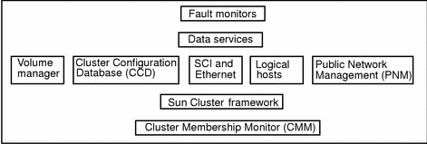
In an HA configuration, the membership monitor, fault monitor, and associated programs allow one Sun Cluster server to take over processing of all data services from the other Sun Cluster server when hardware or software fails. This is accomplished by causing a Sun Cluster server without the failure to take over mastery of the logical host associated with the failed Sun Cluster server. Some types of failures do not cause failover. Disk drive failure does not typically result in a failover--mirroring handles this. Similarly, software failures detected by the fault monitors might cause a data service to be restarted on the same physical node rather than failing over to another node.
1.5.2 Fault Monitor Layer
The fault monitor layer consists of a fault daemon and the programs used to probe various parts of the data service. If the fault monitor layer detects a service failure, it can attempt to restart the service on the same node, or initiate a failover of the logical host, depending on how the data service is configured.
Under certain circumstances a data service fault monitor will not initiate a failover even though there has been an interruption of a service. These exceptions include:
-
File systems under control of a logical host are being checked with fsck(1M).
-
The NFSTM file system is locked by using lockfs(1M).
-
The name service (NIS, NIS+, DNS) is not working. The name service exists outside the Sun Cluster configuration so you must ensure its reliability.
1.5.3 Data Services Layer
Sun Cluster includes a set of data services that have been made highly available by Sun. Sun Cluster provides a fault monitor at the data services layer. The level of fault detection provided by this fault monitor varies depending on the particular data service. The level is dependent on a number of factors; Refer to the Sun Cluster 2.2 System Administration Guide for details on how the fault monitor works with the Sun Cluster data services.
As the fault monitors probe the servers, they use the local7 message facility. Messages generated by this facility can be viewed in the messages files or on the console, depending on how you have messages configured on the servers. See the syslog.conf(4) man page for details on setting up your messages configuration.
1.5.3.1 Data Services Supported by Sun Cluster
Sun Cluster provides HA support for various applications such as relational databases, parallel databases, internet services, and resource management data services. For the current list of data services and supported revision levels, see the Sun Cluster 2.2 Release Notes document or contact your Enterprise Service provider. The following data services are supported with this release of Sun Cluster:
-
Sun Cluster HA for DNS
-
Sun Cluster HA for Informix
-
Sun Cluster HA for Lotus
-
Sun Cluster HA for Netscape
-
Sun Cluster HA for Netscape HTTP
-
Sun Cluster HA for Netscape LDAP
-
Sun Cluster HA for Netscape Mail
-
Sun Cluster HA for Netscape News
-
-
Sun Cluster HA for NFS
-
Sun Cluster HA for Oracle
-
Sun Cluster HA for SAP
-
Sun Cluster HA for Sybase
-
Sun Cluster HA for Tivoli
-
Oracle Parallel Server
-
Informix-Online XPS
1.5.3.2 Data Services API
Sun Cluster software includes an Application Programming Interface (API) permitting existing crash-tolerant data services to be made highly available under the Sun Cluster HA framework. Data services register methods (programs) that are called back by the HA framework at certain key points of cluster reconfigurations. Utilities are provided to permit data service methods to query the state of the Sun Cluster configuration and to initiate takeovers. Additional utilities make it convenient for a data service method to run a program while holding a file lock, run a program under a timeout, or automatically restart a program if it dies.
For more information on the data services API, refer to the Sun Cluster 2.2 API Developer's Guide.
1.5.4 Switch Management Agent
The Switch Management Agent (SMA) software component manages sessions for the SCI links and switches. Similarly, it manages communications over the Ethernet links and switches. In addition, SMA isolates applications from individual link failures and provides the notion of a logical link for all applications.
1.5.5 Cluster SNMP Agent
Sun Cluster includes a Simple Network Management Protocol (SNMP) agent, along with a Management Information Base (MIB), for the cluster. The name of the agent file is snmpd (SNMP daemon) and the name of the MIB is sun.mib.
The Sun Cluster SNMP agent is capable of monitoring several clusters (a maximum of 32) at the same time. In a typical Sun Cluster, you can manage the cluster from the administration workstation or System Service Processor (Sun Enterprise 10000). By installing the Sun Cluster SNMP agent on the administration workstation or System Service Processor, network traffic is regulated and the CPU power of the nodes is not wasted in transmitting SNMP packets.
1.5.6 Cluster Configuration Database
The Cluster Configuration Database (CCD) is a highly available, replicated database that is used to store internal configuration data for Sun Cluster configuration needs. The CCD is for Sun Cluster internal use--it is not a public interface and you should not attempt to update it directly.
The CCD relies on the Cluster Membership Monitor (CMM) service to determine the current cluster membership and determine its consistency domain, that is, the set of nodes that must have a consistent copy of the database and that propagate updates. The CCD database is divided into an Initial (Init) and a Dynamic database.
The purpose of the Init CCD database is storage of non-modifiable boot configuration parameters whose values are set during the CCD package installation (scinstall). The Dynamic CCD contains the remaining database entries. Unlike the Init CCD, entries in the Dynamic CCD can be updated at any time with the restrictions that the CCD database is recovered (that is, the cluster is up) and the CCD has quorum. (See "1.5.6.1 CCD Operation", for the definition of quorum.)
The Init CCD (/etc/opt/SUNWcluster/conf/ccd.database.init) is also used to store data for components that are started before the CCD is up. This means that queries to the Init CCD can occur before the CCD database has recovered and global consistency is checked.
The Dynamic CCD (/etc/opt/SUNWcluster/conf/ccd.database) contains the remaining database entries. The CCD guarantees the consistent replication of the Dynamic CCD across all of the nodes of its consistency domain.
The CCD database is replicated on all the nodes to guarantee its availability in case of a node failure. CCD daemons establish communications among themselves to synchronize and serialize database operations within the CCD consistency domain. Database updates and query operations can be issued from any node--the CCD does not have a single point of control.
In addition, the CCD offers:
-
Cluster-wide repository (the same view from every node)
-
Distributed framework for updates
-
Local consistency (consistency record)
-
Global consistency (automatic replication)
-
-
Database recovery and resynchronization
1.5.6.1 CCD Operation
The CCD guarantees a consistent replication of the database across all the nodes of the elected consistency domain. Only nodes that are found to have a valid copy of the CCD are allowed to be in the cluster. Consistency checks are performed at two levels, local and global. Locally, each replicated database copy has a self-contained consistency record that stores the checksum and length of the database. This consistency record validates the local database copy in case of an update or database recovery. The consistency record timestamps the last update of the database.
The CCD also performs a global consistency check to verify that every node has an identical copy of the database. The CCD daemons exchange and verify their consistency record. During a cluster restart, a quorum voting scheme is used for recovering the database. The recovery process determines how many nodes have a valid copy of the CCD (the local consistency is checked through the consistency record), and how many copies are identical (have the same checksum and length).
A quorum majority (when more than half the nodes are up) must be found within the default consistency domain to guarantee that the CCD copy is current.
Note -
A quorum majority is required to perform updates to the CCD.
The equation Q= [Na/2]+1 specifies the number of nodes required to perform updates to the CCD. Na is the number of nodes physically present in the cluster. These nodes might be physically present, but not running the cluster software.
In the case of a two-node cluster with Cluster Volume Manager or Sun StorEdge Volume Manager, quorum may be maintained with only one node up by the use of a shared CCD volume. In a shared-CCD configuration, one copy of the CCD is kept on the local disk of each node and another copy is kept on in a special disk group that can be shared between the nodes. In normal operation, only the copies on the local disks are used, but if one node fails, the shared CCD is used to maintain CCD quorum with only one node in the cluster. When the failed node rejoins the cluster, it is updated with the current copy of the shared CCD. Refer to Chapter 3, Installing and Configuring Sun Cluster Software, for details on setting up a shared CCD volume in a two-node cluster.
If one node stays up, its valid CCD can be propagated to the newly joining nodes. The CCD recovery algorithm guarantees that the CCD database is up only if a valid copy is found and is correctly replicated on all the nodes. If the recovery fails, you must intervene and decide which one of the CCD copies is the valid one. The elected copy can then be used to restore the database via the ccdadm -r command. See the Sun Cluster 2.2 System Administration Guide for the procedures used to administer the CCD.
Note -
The CCD provides a backup facility, ccdadm(1M), to checkpoint the current content of the database. The backup copy can subsequently be used to restore the database. Refer to the ccdadm(1M) man page for details.
1.5.7 Volume Managers
Sun Cluster supports three volume managers: Solstice DiskSuite, Sun StorEdge Volume Manager (SSVM), and Cluster Volume Manager (CVM). These volume managers provide mirroring, concatenating, and striping for use by Sun Cluster. SSVM and CVM also enable you to set up and administer RAID5 under Sun Cluster. Volume managers organize disks into disk groups that can then be administered as a unit.
The Sun StorEdge A3000 disk expansion unit also has the capability of mirroring, concatenation, and striping all within the Sun StorEdge A3000 hardware. You must use SSVM or CVM to manage disksets on the Sun StorEdge A3000. You also must use SSVM or CVM if you want to concatenate or stripe over several Sun StorEdge A3000s or mirror between Sun StorEdge A3000s.
For information on your particular volume manager refer to your volume manager documentation.
1.5.7.1 Disk Groups
Disk groups are sets of mirrored or RAID5 configurations composed of shared disks. All data service and parallel database data is stored in disk groups on the shared disks. Mirrors within disk groups are generally organized such that each half of a mirror is physically located within a separate disk expansion unit and connected to a separate controller or host adapter. This eliminates a single disk or disk expansion unit as a single point of failure.
Disk groups may either be used for raw data storage, or for file systems, or both.
1.5.8 Logical Hosts
In HA configurations, Sun Cluster supports the concept of a logical host. A logical host is a set of resources that can move as a unit between Sun Cluster servers. In Sun Cluster, the resources include a collection of network host names and their associated IP addresses plus one or more groups of disks (a disk group). In non-HA cluster environments, such as OPS configurations, an IP address is permanently mapped to a particular host system. Client applications access their data by specifying the IP address of the host running the server application.
In Sun Cluster, an IP address is assigned to a logical host and is temporarily associated with whatever host system the application server is currently running on. These IP addresses are relocatable--that is, they can move from one node to another. In the Sun Cluster environment, clients specify the logical hosts's relocatable IP addresses to connect to an application rather than the IP address of the physical host system.
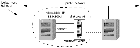
In Figure 1-18, logical host hahost1 is defined by the network host name hahost1, the relocatable IP address 192.9.200.1, and the disk group diskgroup1. Note that the logical host name and the disk group name do not have to be the same.
Figure 1-18 Logical Hosts
Logical hosts have one logical host name and one relocatable IP address on each public network. The name by which a logical host is known on the primary public network is its primary logical host name. The names by which logical hosts are known on secondary public networks are secondary logical host names. Figure 1-19 shows the host names and relocatable IP addresses for the two logical hosts with primary logical host names hahost1 and hahost2. In this figure, secondary logical host names use a suffix that consists of the last component of the network number (201). For example, hahost1-201 is the secondary logical host name for logical host hahost1.
Figure 1-19 Logical Hosts on Multiple Public Networks

Logical hosts are mastered by physical hosts. Only the physical host that currently masters a logical host can access the logical host's disk groups. A physical host can master multiple logical hosts, but each logical host can be mastered by only one physical host at a time. Any physical host that is capable of mastering a particular logical host is referred to as a potential master of that logical host.
A data service makes its services accessible to clients on the network by advertising a well-known logical host name associated with the physical host. The logical host names are part of the IP name space at a site, but do not have a specific physical dedicated to them. The clients use these logical host names to access the services provided by the data service.
Figure 1-20 shows a configuration with multiple data services located on a single logical host's disk group. In this example, assume logical host hahost2 is currently mastered by phys-hahost2. In this configuration, if phys-hahost2 fails, both of the Sun Cluster HA for Netscape data services (dg2-http and dg2-news) will fail over to phys-hahost1.
Figure 1-20 Logical Hosts, Disksets, and Data Service Files

Read the discussion in Chapter 2, Planning the Configuration, for a list of issues to consider when deciding how to configure your data services on the logical hosts.
1.5.9 Public Network Management (PNM)
Some types of failures cause all logical hosts residing on that node, to be transferred to another node. The failure of a network adapter card, connector or cable between the node and the public network need not result in a node failover. Public Network Management (PNM) software in the Sun Cluster framework allows network adapters to be grouped into sets such that if one fails, another in its group takes over the servicing of network requests. A user will experience only a small delay while the error detection and failover mechanisms are in process.
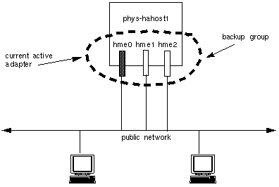
In a configuration using PNM, there are multiple network interfaces on the same subnet. These interfaces make up a backup group. At any point, a network adapter can only be in one backup group and only one adapter within a backup group is active. When the current active adapter fails, the PNM software automatically switches the network services to use another adapter in the backup group. All adapters used for public networks should be in a backup group.
Note -
Backup groups are also used to monitor the public nets even when same-node failover adapters are not present.
Figure 1-21 Network Adapter Failover Configuration
Refer to the Sun Cluster 2.2 System Administration Guide for information on setting up and administering PNM.
1.5.10 System Failover and Switchover
If a node fails in the Sun Cluster HA configuration, the data services running on the failed node are moved automatically to a working node in the failed node's server set. The failover software moves the IP addresses of the logical host(s) from the failed host to the working node. All data services that were running on logical hosts mastered by the failed host are moved.
The system administrator can manually switch over a logical host. The difference between failover and switchover is that the former is handled automatically by the Sun Cluster software when a node fails and the latter is done manually by the system administrator. A switchover might be performed to do periodic maintenance or to upgrade software on the cluster nodes.
Figure 1-22 shows a two-node configuration in normal operation. Note that each physical host masters a logical host (solid lines). The figure shows two clients accessing separate data services located on the two logical hosts.
Figure 1-22 Symmetric Configuration Before Failover or Switchover
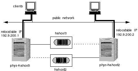
If phys-hahost1 fails, the logical host hahost1 will be relocated to phys-hahost2. The relocatable IP address for hahost1 will move to phys-hahost2 and data service requests will be directed to phys-hahost2. The clients accessing data on hahost1 will experience a short delay while a cluster reconfiguration occurs. The new configuration that results is shown in Figure 1-23.
Note that the client system that previously accessed logical host hahost1 on phys-hahost1 continues to access the same logical host but now on phys-hahost2. In the failover case, this is automatically accomplished by the cluster reconfiguration. As a result of the failover, phys-hahost2 now masters both logical hosts hahost1 and hahost2. The associated disksets are now accessible only through phys-hahost2.
Figure 1-23 Symmetric Configuration After Failover or Switchover
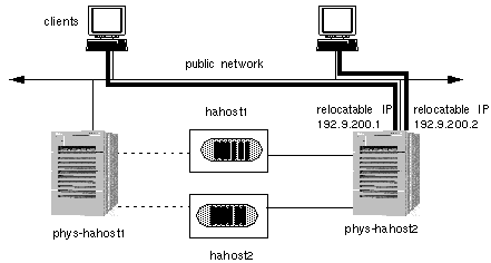
1.5.10.1 Partial Failover
The fact that one physical host can master multiple logical hosts permits partial failover of data services. Figure 1-24 shows a star configuration that includes three physical hosts and five logical hosts. In this figure, the lines connecting the physical hosts and the logical hosts indicate which physical host currently masters which logical host (and disk groups).
The four logical hosts mastered by phys-hahost1 (solid lines) can fail over individually to the hot-standby server. Note that the hot-standby server in Figure 1-24 has physical connections to all multihost disks, but currently does not master any logical hosts.
Figure 1-24 Before Partial Failover with Multiple Logical Hosts
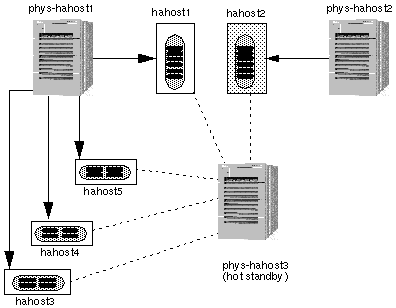
Figure 1-25 shows the results of a partial failover where hahost5 has failed over to the hot-standby server.
During partial failover, phys-hahost1 relinquishes mastery of logical host hahost5. Then phys-hahost3, the hot-standby server, takes over mastery of this logical host.
Figure 1-25 After Partial Failover with Multiple Logical Hosts
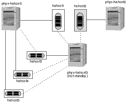
You can control which data services fail over together by placing them on the same logical host. Refer to Chapter 2, Planning the Configuration, for a discussion of the issues associated with combining or separating data services on logical hosts.
1.5.10.2 Failover With Parallel Databases
In the parallel database environment, there is no concept of a logical host. However, there is the notion of relocatable IP addresses that can migrate between nodes in the event of a node failure. For more information about relocatable IP addresses and failover, see "1.5.8 Logical Hosts", and "1.5.10 System Failover and Switchover".
- © 2010, Oracle Corporation and/or its affiliates
