1.2 Hardware Configuration Components
HA and parallel database configurations are composed of similar hardware and software components. The hardware components include:
-
Cluster nodes
-
Private interconnects
-
Public networks
-
Local disks
-
Multihost disks
-
Terminal Concentrator or System Service Processor (SSP)
-
Administrative Workstation
Details on all of these components are described in the following sections.
1.2.1 Cluster Nodes
Cluster nodes are the Sun EnterpriseTM servers that run data services and parallel database applications. Sun Cluster supports 2-, 3-, and 4-node clusters.
1.2.2 Cluster Interconnect
The cluster interconnect provides a reliable internode communication channel used for vital locking and heartbeat information. The interconnect is used for maintaining cluster availability, synchronization, and integrity. The cluster interconnect is composed of two private links. These links are redundant; only one is required for cluster operation. If all nodes are up and a single private interconnect is lost, cluster operation will continue. However, when a node joins the cluster, both private interconnects must be operational for the join to complete successfully.
Note -
By convention throughout this guide the network adapter interfaces hme1 and hme2 are shown as the cluster interconnect. Your interface names can vary depending on your hardware platform and your private network configuration. The requirement is that the two private interconnects do not share the same controller and thus cannot be disrupted by a single point of failure.
Clusters can use either the Scalable Coherent Interface (SCI) or Fast Ethernet as the private interconnect medium. However, support for mixed configurations (that is, both SCI and Ethernet private interconnects in the same cluster) is not supported.
1.2.2.1 The Switch Management Agent
The Switch Management Agent (SMA) is a cluster module that maintains communication channels over the private interconnect. It monitors the private interconnect and performs a failover of the logical adapter on the surviving private network if it detects a failure. In the case of more than one failure, SMA notifies the Cluster Membership Monitor which will take any action needed to change the cluster membership.
Clustered environments have different communication needs depending on the types of data services they support. Clusters providing only HA data services need only the heartbeat and minimal cluster configuration traffic over the private interconnect, and for these configurations Fast Ethernet is more than adequate. Clusters providing parallel database services send substantial amounts of traffic over the private interconnect. These applications benefit from the increased throughput of SCI.
SMA for SCI Clusters
The Scalable Coherent Interface (SCI) is a memory-based high-speed interconnect that enables sharing of memory among cluster nodes. The SCI private interconnect consists of Transmission Control Protocol/Internet Protocol (TCP/IP) network interfaces based on SCI.
Clusters of all sizes may be connected through a switch or hub. However, only two-node clusters may be connected point-to-point. The Switch Management Agent (SMA) software component manages sessions for the SCI links and switches.
There are three basic SCI topologies supported in Sun Cluster (Figure 1-1 and Figure 1-2):
-
Three- or four-node cluster that requires two SCI switches
-
Two-node cluster connected point-to-point
-
Two-node switched cluster (degenerate case of the four-node cluster that allows for future expansion of cluster nodes with minimal interruption)
Figure 1-1 SCI Cluster Topology for Four Nodes

Figure 1-2 SCI Cluster Topologies for Two Nodes

SMA for Ethernet Clusters
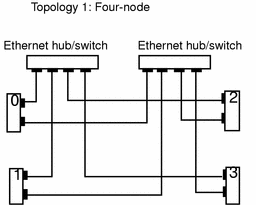
Clusters of all sizes may be connected through a switch or hub. However, only two-node clusters may be connected point-to-point. The Switch Management Agent (SMA) software component manages communications over the Ethernet switches or hubs.
There are three basic Ethernet topologies supported in Sun Cluster (Figure 1-3 and Figure 1-4):
-
Three- or four-node cluster that requires two Ethernet switches or hubs
-
Two-node point-to-point cluster
-
Two-node cluster with Ethernet switches or hubs (a degenerate case of the four-node cluster that allows for future expansion of cluster nodes with minimal interruption)
Figure 1-3 Ethernet Cluster Topology for Four Nodes

Figure 1-4 Ethernet Cluster Topologies for Two Nodes

1.2.3 /etc/nsswitch.conf File Entries
You must modify the /etc/nsswitch.conf file to ensure that "services," "group," and "hosts" lookups are always directed to the /etc files. This is done as part of the Sun Cluster installation described in Chapter 3, Installing and Configuring Sun Cluster Software.
The following shows an example /etc/nsswitch.conf file using NIS+ as the name service:
services: files nisplus |
This entry must be before other services entries. Refer to the nsswitch.conf(4) man page for more information.
You must update /etc/nsswitch.conf manually by using your favorite editor. You can use the Cluster Console to update all nodes at one time. Refer to the chapter on Sun Cluster administration tools in the Sun Cluster 2.2 System Administration Guide for more information on the Cluster Console.
1.2.4 Public Networks
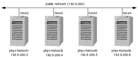
Cluster access to a Sun cluster is achieved by connecting the cluster nodes to one or more public networks. You can have any number of public networks attached to your cluster nodes, but the public network(s) must connect to every node in the cluster, regardless of the cluster topology. Figure 1-5 shows a four-node configuration with a single public network (192.9.200). Each physical host has an IP address on the public network.
One public network is designated as the primary public network and other public networks are called secondary public networks. Each network is also referred to as a subnetwork or subnet. The physical network adapter (hme0) is also shown in Figure 1-5. By convention throughout this guide, hme0 is shown for the primary public network interface. This can vary depending on your hardware platform and your public network configuration.
Figure 1-5 Four-Node Cluster With a Single Public Network Connection

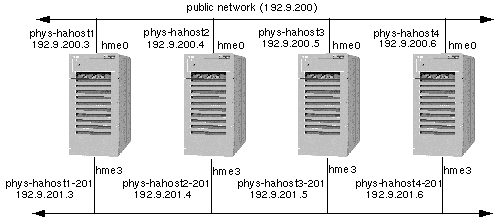
Figure 1-6 shows the same configuration with the addition of a second public network (192.9.201). An additional physical host name and IP address must be assigned on each Sun Cluster server for each additional public network.
The names by which physical hosts are known on the public network are their primary physical host names. The names by which physical hosts are known on a secondary public network are their secondary physical host names. In Figure 1-6 the primary physical host names are labeled phys-hahost[1-4]. The secondary physical host names are labeled phys-hahost[1-4]-201, where the suffix -201 identifies the network. Physical host naming conventions are described in more detail in Chapter 2, Planning the Configuration.
The network adapter hme3 is shown to be used by all nodes as the interface to the secondary public network. The adapter interface can be any suitable interface; hme3 is shown here as an example.
Figure 1-6 Four-Node Cluster With Two Public Networks

1.2.5 Local Disks
Each Sun Cluster server has one or more disks that are accessible only from that server. These are called local disks. They contain the Sun Cluster software environment and the Solaris operating environment.
Note -
Sun Cluster supports the capability to boot from a disk inside a multihost SPARCstorageTM Array (SSA) and does not require a private boot disk. The Sun Cluster software supports SSAs that have both local (private) and shared disks.
Figure 1-7 shows a two-node configuration including the local disks.
Local disks can be mirrored, but mirroring is not required. Refer to Chapter 2, Planning the Configuration, for a detailed discussion about mirroring the local disks.
1.2.6 Multihost Disks
In all Sun Cluster configurations, two or more nodes are physically connected to a set of shared, or multihost, disks. The shared disks are grouped across disk expansion units. Disk expansion units are the physical disk enclosures. Sun Cluster supports various disk expansion units: Sun StorEdgeTM MultiPack, Sun StorEdge A3000, and Sun StorEdge A5000 units, for example. Figure 1-7 shows two hosts, both physically connected to a set of disk expansion units. It is not required that all cluster nodes are physically connected to all disk expansion units.
In HA configurations, the multihost disks contain the data for highly available data services. A server can access data on a multihost disk when it is the current master of that disk. In the event of failure of one of the Sun Cluster servers, the data services fail over to another server in the cluster. At failover, the data services that were running on the failed node are started on another node without user intervention and with only minor service interruption. The system administrator can switch over data services manually at any time from one Sun Cluster server to another. Refer to "1.5.10 System Failover and Switchover", for more details on failover and switchover.
In parallel database configurations, the multihost disks contain the data used by the relational database application. Multiple servers access the multihost disk simultaneously. User processes are prevented from corrupting shared data by the Oracle UNIX Dynamic Lock Manager (DLM). If one server connected to a multihost disk fails, the cluster software recognizes the failure and routes user queries through one of the remaining servers.
All multihost disks with the exception of the Sun StorEdge A3000 (with RAID5) must be mirrored. Figure 1-7 shows a multihost disk configuration.
Figure 1-7 Local and Multihost Disks

1.2.7 Terminal Concentrator or System Service Processor and Administrative Workstation
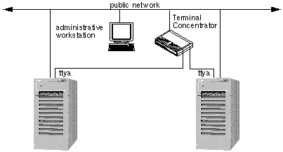
The Terminal Concentrator is a device used to connect all cluster node console serial ports to a single workstation. The Terminal Concentrator turns the console serial ports on cluster nodes into telnet-accessible devices. You can telnet to an address on the Terminal Concentrator, and see a boot-PROM-prompt capable console window.
The System Service Processor (SSP) provides console access for Sun Enterprise 10000 servers. The SSP is a Solaris workstation on an Ethernet network that is especially configured to support the Sun Enterprise 10000. The SSP is used as the administrative workstation for Sun Cluster configurations using the Sun Enterprise 10000. Using the Sun Enterprise 10000 Network Console feature, any workstation in the network can open a host console session.
The Cluster Console connects a telnet(1M) session to the SSP, allowing you to log into the SSP and start a netcon session to control the domain. Refer to your Sun Enterprise 10000 documentation for more information on the SSP.
The Terminal Concentrator and System Service Processor are used to shut down nodes in certain failure scenarios as part of the failure fencing process. See "1.3.4.1 Failure Fencing (SSVM and CVM)", for more details.
The administrative workstation is used to provide console interfaces from all of the nodes in the cluster. This can be any workstation capable of running a Cluster Console session.
See the Sun Cluster 2.2 System Administration Guide and the Terminal Concentrator documentation for further information on these interfaces.
Figure 1-8 Terminal Concentrator and Administrative Workstation

- © 2010, Oracle Corporation and/or its affiliates
