1.5 Software Configuration Components
Sun Cluster includes the following software components:
-
Cluster framework
-
Data services
Associated with these software components are the following logical components:
-
Logical hosts
-
Disk groups
These components are described in the following sections.
1.5.1 Cluster Framework
Figure 1-17 shows the approximate layering of the various components that constitute the framework required to support HA data services in Sun Cluster. This diagram does not illustrate the relationship between the various components of Sun Cluster. The innermost core consists of the Cluster Membership Monitor (CMM), which keeps track of the current cluster membership. Whenever nodes leave or rejoin the cluster, the CMM on the cluster nodes go through a distributed membership protocol to agree on the new cluster membership. Once the new membership is established, the CMM orchestrates the reconfiguration of the other cluster components through the Sun Cluster framework.
Figure 1-17 Sun Cluster Software Components
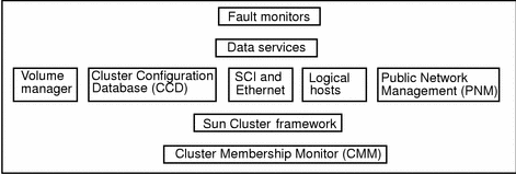
In an HA configuration, the membership monitor, fault monitor, and associated programs allow one Sun Cluster server to take over processing of all data services from the other Sun Cluster server when hardware or software fails. This is accomplished by causing a Sun Cluster server without the failure to take over mastery of the logical host associated with the failed Sun Cluster server. Some types of failures do not cause failover. Disk drive failure does not typically result in a failover--mirroring handles this. Similarly, software failures detected by the fault monitors might cause a data service to be restarted on the same physical node rather than failing over to another node.
1.5.2 Fault Monitor Layer
The fault monitor layer consists of a fault daemon and the programs used to probe various parts of the data service. If the fault monitor layer detects a service failure, it can attempt to restart the service on the same node, or initiate a failover of the logical host, depending on how the data service is configured.
Under certain circumstances a data service fault monitor will not initiate a failover even though there has been an interruption of a service. These exceptions include:
-
File systems under control of a logical host are being checked with fsck(1M).
-
The NFSTM file system is locked by using lockfs(1M).
-
The name service (NIS, NIS+, DNS) is not working. The name service exists outside the Sun Cluster configuration so you must ensure its reliability.
1.5.3 Data Services Layer
Sun Cluster includes a set of data services that have been made highly available by Sun. Sun Cluster provides a fault monitor at the data services layer. The level of fault detection provided by this fault monitor varies depending on the particular data service. The level is dependent on a number of factors; Refer to the Sun Cluster 2.2 System Administration Guide for details on how the fault monitor works with the Sun Cluster data services.
As the fault monitors probe the servers, they use the local7 message facility. Messages generated by this facility can be viewed in the messages files or on the console, depending on how you have messages configured on the servers. See the syslog.conf(4) man page for details on setting up your messages configuration.
1.5.3.1 Data Services Supported by Sun Cluster
Sun Cluster provides HA support for various applications such as relational databases, parallel databases, internet services, and resource management data services. For the current list of data services and supported revision levels, see the Sun Cluster 2.2 Release Notes document or contact your Enterprise Service provider. The following data services are supported with this release of Sun Cluster:
-
Sun Cluster HA for DNS
-
Sun Cluster HA for Informix
-
Sun Cluster HA for Lotus
-
Sun Cluster HA for Netscape
-
Sun Cluster HA for Netscape HTTP
-
Sun Cluster HA for Netscape LDAP
-
Sun Cluster HA for Netscape Mail
-
Sun Cluster HA for Netscape News
-
-
Sun Cluster HA for NFS
-
Sun Cluster HA for Oracle
-
Sun Cluster HA for SAP
-
Sun Cluster HA for Sybase
-
Sun Cluster HA for Tivoli
-
Oracle Parallel Server
-
Informix-Online XPS
1.5.3.2 Data Services API
Sun Cluster software includes an Application Programming Interface (API) permitting existing crash-tolerant data services to be made highly available under the Sun Cluster HA framework. Data services register methods (programs) that are called back by the HA framework at certain key points of cluster reconfigurations. Utilities are provided to permit data service methods to query the state of the Sun Cluster configuration and to initiate takeovers. Additional utilities make it convenient for a data service method to run a program while holding a file lock, run a program under a timeout, or automatically restart a program if it dies.
For more information on the data services API, refer to the Sun Cluster 2.2 API Developer's Guide.
1.5.4 Switch Management Agent
The Switch Management Agent (SMA) software component manages sessions for the SCI links and switches. Similarly, it manages communications over the Ethernet links and switches. In addition, SMA isolates applications from individual link failures and provides the notion of a logical link for all applications.
1.5.5 Cluster SNMP Agent
Sun Cluster includes a Simple Network Management Protocol (SNMP) agent, along with a Management Information Base (MIB), for the cluster. The name of the agent file is snmpd (SNMP daemon) and the name of the MIB is sun.mib.
The Sun Cluster SNMP agent is capable of monitoring several clusters (a maximum of 32) at the same time. In a typical Sun Cluster, you can manage the cluster from the administration workstation or System Service Processor (Sun Enterprise 10000). By installing the Sun Cluster SNMP agent on the administration workstation or System Service Processor, network traffic is regulated and the CPU power of the nodes is not wasted in transmitting SNMP packets.
1.5.6 Cluster Configuration Database
The Cluster Configuration Database (CCD) is a highly available, replicated database that is used to store internal configuration data for Sun Cluster configuration needs. The CCD is for Sun Cluster internal use--it is not a public interface and you should not attempt to update it directly.
The CCD relies on the Cluster Membership Monitor (CMM) service to determine the current cluster membership and determine its consistency domain, that is, the set of nodes that must have a consistent copy of the database and that propagate updates. The CCD database is divided into an Initial (Init) and a Dynamic database.
The purpose of the Init CCD database is storage of non-modifiable boot configuration parameters whose values are set during the CCD package installation (scinstall). The Dynamic CCD contains the remaining database entries. Unlike the Init CCD, entries in the Dynamic CCD can be updated at any time with the restrictions that the CCD database is recovered (that is, the cluster is up) and the CCD has quorum. (See "1.5.6.1 CCD Operation", for the definition of quorum.)
The Init CCD (/etc/opt/SUNWcluster/conf/ccd.database.init) is also used to store data for components that are started before the CCD is up. This means that queries to the Init CCD can occur before the CCD database has recovered and global consistency is checked.
The Dynamic CCD (/etc/opt/SUNWcluster/conf/ccd.database) contains the remaining database entries. The CCD guarantees the consistent replication of the Dynamic CCD across all of the nodes of its consistency domain.
The CCD database is replicated on all the nodes to guarantee its availability in case of a node failure. CCD daemons establish communications among themselves to synchronize and serialize database operations within the CCD consistency domain. Database updates and query operations can be issued from any node--the CCD does not have a single point of control.
In addition, the CCD offers:
-
Cluster-wide repository (the same view from every node)
-
Distributed framework for updates
-
Local consistency (consistency record)
-
Global consistency (automatic replication)
-
-
Database recovery and resynchronization
1.5.6.1 CCD Operation
The CCD guarantees a consistent replication of the database across all the nodes of the elected consistency domain. Only nodes that are found to have a valid copy of the CCD are allowed to be in the cluster. Consistency checks are performed at two levels, local and global. Locally, each replicated database copy has a self-contained consistency record that stores the checksum and length of the database. This consistency record validates the local database copy in case of an update or database recovery. The consistency record timestamps the last update of the database.
The CCD also performs a global consistency check to verify that every node has an identical copy of the database. The CCD daemons exchange and verify their consistency record. During a cluster restart, a quorum voting scheme is used for recovering the database. The recovery process determines how many nodes have a valid copy of the CCD (the local consistency is checked through the consistency record), and how many copies are identical (have the same checksum and length).
A quorum majority (when more than half the nodes are up) must be found within the default consistency domain to guarantee that the CCD copy is current.
Note -
A quorum majority is required to perform updates to the CCD.
The equation Q= [Na/2]+1 specifies the number of nodes required to perform updates to the CCD. Na is the number of nodes physically present in the cluster. These nodes might be physically present, but not running the cluster software.
In the case of a two-node cluster with Cluster Volume Manager or Sun StorEdge Volume Manager, quorum may be maintained with only one node up by the use of a shared CCD volume. In a shared-CCD configuration, one copy of the CCD is kept on the local disk of each node and another copy is kept on in a special disk group that can be shared between the nodes. In normal operation, only the copies on the local disks are used, but if one node fails, the shared CCD is used to maintain CCD quorum with only one node in the cluster. When the failed node rejoins the cluster, it is updated with the current copy of the shared CCD. Refer to Chapter 3, Installing and Configuring Sun Cluster Software, for details on setting up a shared CCD volume in a two-node cluster.
If one node stays up, its valid CCD can be propagated to the newly joining nodes. The CCD recovery algorithm guarantees that the CCD database is up only if a valid copy is found and is correctly replicated on all the nodes. If the recovery fails, you must intervene and decide which one of the CCD copies is the valid one. The elected copy can then be used to restore the database via the ccdadm -r command. See the Sun Cluster 2.2 System Administration Guide for the procedures used to administer the CCD.
Note -
The CCD provides a backup facility, ccdadm(1M), to checkpoint the current content of the database. The backup copy can subsequently be used to restore the database. Refer to the ccdadm(1M) man page for details.
1.5.7 Volume Managers
Sun Cluster supports three volume managers: Solstice DiskSuite, Sun StorEdge Volume Manager (SSVM), and Cluster Volume Manager (CVM). These volume managers provide mirroring, concatenating, and striping for use by Sun Cluster. SSVM and CVM also enable you to set up and administer RAID5 under Sun Cluster. Volume managers organize disks into disk groups that can then be administered as a unit.
The Sun StorEdge A3000 disk expansion unit also has the capability of mirroring, concatenation, and striping all within the Sun StorEdge A3000 hardware. You must use SSVM or CVM to manage disksets on the Sun StorEdge A3000. You also must use SSVM or CVM if you want to concatenate or stripe over several Sun StorEdge A3000s or mirror between Sun StorEdge A3000s.
For information on your particular volume manager refer to your volume manager documentation.
1.5.7.1 Disk Groups
Disk groups are sets of mirrored or RAID5 configurations composed of shared disks. All data service and parallel database data is stored in disk groups on the shared disks. Mirrors within disk groups are generally organized such that each half of a mirror is physically located within a separate disk expansion unit and connected to a separate controller or host adapter. This eliminates a single disk or disk expansion unit as a single point of failure.
Disk groups may either be used for raw data storage, or for file systems, or both.
1.5.8 Logical Hosts
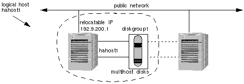
In HA configurations, Sun Cluster supports the concept of a logical host. A logical host is a set of resources that can move as a unit between Sun Cluster servers. In Sun Cluster, the resources include a collection of network host names and their associated IP addresses plus one or more groups of disks (a disk group). In non-HA cluster environments, such as OPS configurations, an IP address is permanently mapped to a particular host system. Client applications access their data by specifying the IP address of the host running the server application.
In Sun Cluster, an IP address is assigned to a logical host and is temporarily associated with whatever host system the application server is currently running on. These IP addresses are relocatable--that is, they can move from one node to another. In the Sun Cluster environment, clients specify the logical hosts's relocatable IP addresses to connect to an application rather than the IP address of the physical host system.
In Figure 1-18, logical host hahost1 is defined by the network host name hahost1, the relocatable IP address 192.9.200.1, and the disk group diskgroup1. Note that the logical host name and the disk group name do not have to be the same.
Figure 1-18 Logical Hosts
Logical hosts have one logical host name and one relocatable IP address on each public network. The name by which a logical host is known on the primary public network is its primary logical host name. The names by which logical hosts are known on secondary public networks are secondary logical host names. Figure 1-19 shows the host names and relocatable IP addresses for the two logical hosts with primary logical host names hahost1 and hahost2. In this figure, secondary logical host names use a suffix that consists of the last component of the network number (201). For example, hahost1-201 is the secondary logical host name for logical host hahost1.
Figure 1-19 Logical Hosts on Multiple Public Networks

Logical hosts are mastered by physical hosts. Only the physical host that currently masters a logical host can access the logical host's disk groups. A physical host can master multiple logical hosts, but each logical host can be mastered by only one physical host at a time. Any physical host that is capable of mastering a particular logical host is referred to as a potential master of that logical host.
A data service makes its services accessible to clients on the network by advertising a well-known logical host name associated with the physical host. The logical host names are part of the IP name space at a site, but do not have a specific physical dedicated to them. The clients use these logical host names to access the services provided by the data service.
Figure 1-20 shows a configuration with multiple data services located on a single logical host's disk group. In this example, assume logical host hahost2 is currently mastered by phys-hahost2. In this configuration, if phys-hahost2 fails, both of the Sun Cluster HA for Netscape data services (dg2-http and dg2-news) will fail over to phys-hahost1.
Figure 1-20 Logical Hosts, Disksets, and Data Service Files

Read the discussion in Chapter 2, Planning the Configuration, for a list of issues to consider when deciding how to configure your data services on the logical hosts.
1.5.9 Public Network Management (PNM)
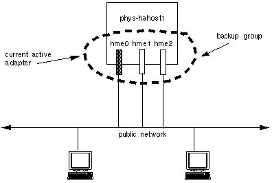
Some types of failures cause all logical hosts residing on that node, to be transferred to another node. The failure of a network adapter card, connector or cable between the node and the public network need not result in a node failover. Public Network Management (PNM) software in the Sun Cluster framework allows network adapters to be grouped into sets such that if one fails, another in its group takes over the servicing of network requests. A user will experience only a small delay while the error detection and failover mechanisms are in process.
In a configuration using PNM, there are multiple network interfaces on the same subnet. These interfaces make up a backup group. At any point, a network adapter can only be in one backup group and only one adapter within a backup group is active. When the current active adapter fails, the PNM software automatically switches the network services to use another adapter in the backup group. All adapters used for public networks should be in a backup group.
Note -
Backup groups are also used to monitor the public nets even when same-node failover adapters are not present.
Figure 1-21 Network Adapter Failover Configuration
Refer to the Sun Cluster 2.2 System Administration Guide for information on setting up and administering PNM.
1.5.10 System Failover and Switchover
If a node fails in the Sun Cluster HA configuration, the data services running on the failed node are moved automatically to a working node in the failed node's server set. The failover software moves the IP addresses of the logical host(s) from the failed host to the working node. All data services that were running on logical hosts mastered by the failed host are moved.
The system administrator can manually switch over a logical host. The difference between failover and switchover is that the former is handled automatically by the Sun Cluster software when a node fails and the latter is done manually by the system administrator. A switchover might be performed to do periodic maintenance or to upgrade software on the cluster nodes.
Figure 1-22 shows a two-node configuration in normal operation. Note that each physical host masters a logical host (solid lines). The figure shows two clients accessing separate data services located on the two logical hosts.
Figure 1-22 Symmetric Configuration Before Failover or Switchover
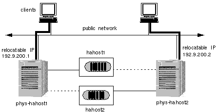
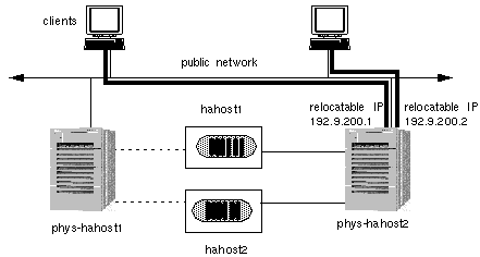
If phys-hahost1 fails, the logical host hahost1 will be relocated to phys-hahost2. The relocatable IP address for hahost1 will move to phys-hahost2 and data service requests will be directed to phys-hahost2. The clients accessing data on hahost1 will experience a short delay while a cluster reconfiguration occurs. The new configuration that results is shown in Figure 1-23.
Note that the client system that previously accessed logical host hahost1 on phys-hahost1 continues to access the same logical host but now on phys-hahost2. In the failover case, this is automatically accomplished by the cluster reconfiguration. As a result of the failover, phys-hahost2 now masters both logical hosts hahost1 and hahost2. The associated disksets are now accessible only through phys-hahost2.
Figure 1-23 Symmetric Configuration After Failover or Switchover
1.5.10.1 Partial Failover
The fact that one physical host can master multiple logical hosts permits partial failover of data services. Figure 1-24 shows a star configuration that includes three physical hosts and five logical hosts. In this figure, the lines connecting the physical hosts and the logical hosts indicate which physical host currently masters which logical host (and disk groups).
The four logical hosts mastered by phys-hahost1 (solid lines) can fail over individually to the hot-standby server. Note that the hot-standby server in Figure 1-24 has physical connections to all multihost disks, but currently does not master any logical hosts.
Figure 1-24 Before Partial Failover with Multiple Logical Hosts
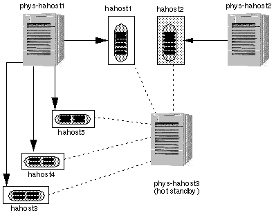
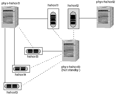
Figure 1-25 shows the results of a partial failover where hahost5 has failed over to the hot-standby server.
During partial failover, phys-hahost1 relinquishes mastery of logical host hahost5. Then phys-hahost3, the hot-standby server, takes over mastery of this logical host.
Figure 1-25 After Partial Failover with Multiple Logical Hosts
You can control which data services fail over together by placing them on the same logical host. Refer to Chapter 2, Planning the Configuration, for a discussion of the issues associated with combining or separating data services on logical hosts.
1.5.10.2 Failover With Parallel Databases
In the parallel database environment, there is no concept of a logical host. However, there is the notion of relocatable IP addresses that can migrate between nodes in the event of a node failure. For more information about relocatable IP addresses and failover, see "1.5.8 Logical Hosts", and "1.5.10 System Failover and Switchover".
- © 2010, Oracle Corporation and/or its affiliates
